
Impedance adjustment circuit and integrated circuit device

a technology of impedance adjustment and integrated circuit, which is applied in the direction of logic circuits, pulse techniques, and increasing modifications to ensure reliability, can solve the problems of inability to accurately detect differential circuits, inability to accommodate transistors, and increased power consumption, so as to reduce the accuracy of impedance adjustment and eliminate the effect of differential circuit misdetection

Inactive Publication Date: 2008-10-28
NEC CORP
View PDF9 Cites 8 Cited by
  • Summary
  • Abstract
  • Description
  • Claims
  • Application Information

AI Technical Summary

Benefits of technology

[0008]An object of the present invention is to provide an impedance adjustment circuit that can inhibit a decrease in impedance adjustment precision caused by variability within the chip, and to provide an integrated circuit device in which the impedance adjustment circuit is mounted.
[0010]In the present invention, the effect of misdetections can be eliminated and accurate comparison results can be output using a method in which a reference electric potential and the electric potential that corresponds to the simulation result are compared by selecting the majority from among the individual comparison results that are produced by three or more differential circuits.
[0015]In accordance with the present invention, the effect of misdetections of the differential circuits can be eliminated, accurate comparison results can be output, and a reduction in the impedance adjustment precision due to variability within the chip can be inhibited by the comparator circuit taking the majority from among three differential circuits.

Problems solved by technology

If the impedance of the transmission lines and the impedance of the load circuit do not match, reflected wave is created at the boundary between the transmission lines and the load circuit, and the reflected wave causes the input buffer circuit to malfunction.
However, this makes it more difficult to accommodate the transistor in the LSI area and causes the through-current, noise, and power consumption to increase.
However, the prior art has the following drawbacks.
With current technology, however, device variability within the chip is becoming more noticeable due to smaller integrated circuits, and there is a new need to consider the variability when circuits are designed.
Due to such variability, differential circuits that detect an electric potential difference of several millivolts are increasingly no longer able to be fabricated by the same convention circuit methods, and it has become difficult to achieve the required impedance adjustment precision.

Method used


Image

  • Impedance adjustment circuit and integrated circuit device
  • Impedance adjustment circuit and integrated circuit device
  • Impedance adjustment circuit and integrated circuit device

Examples


Embodiment Construction

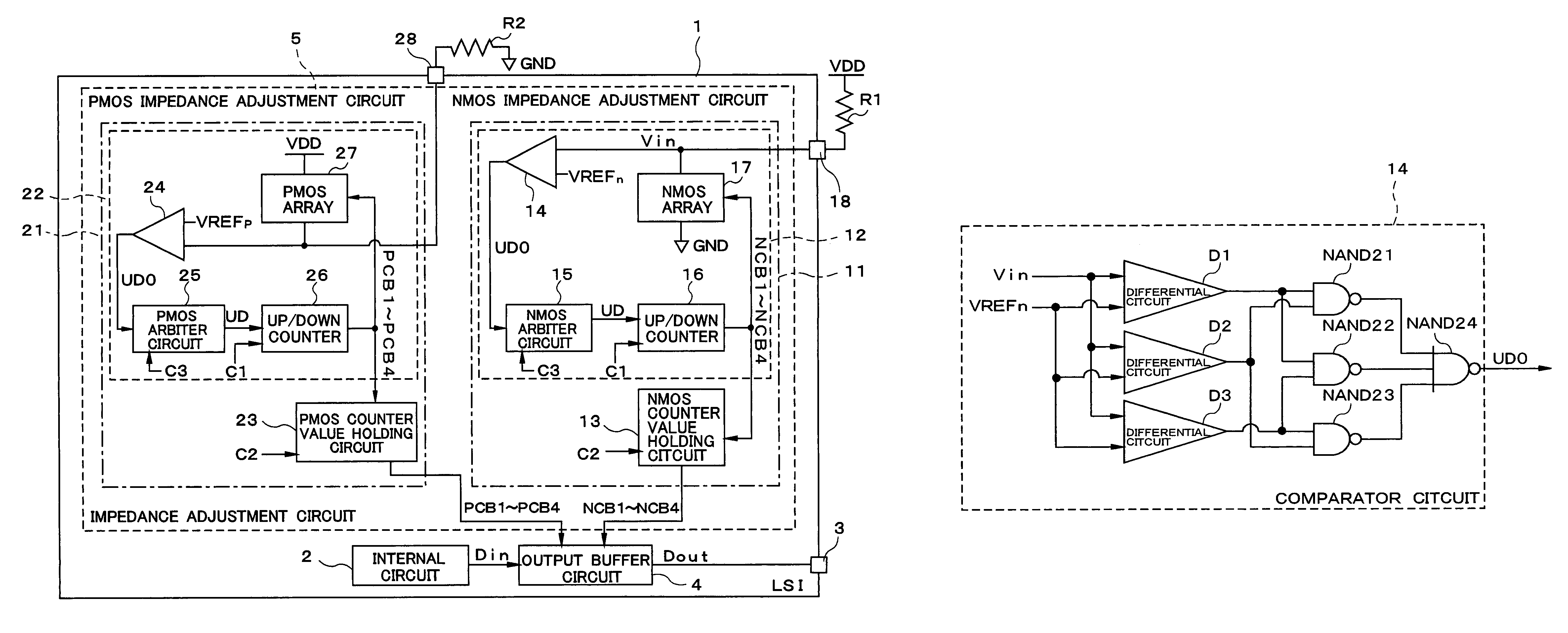
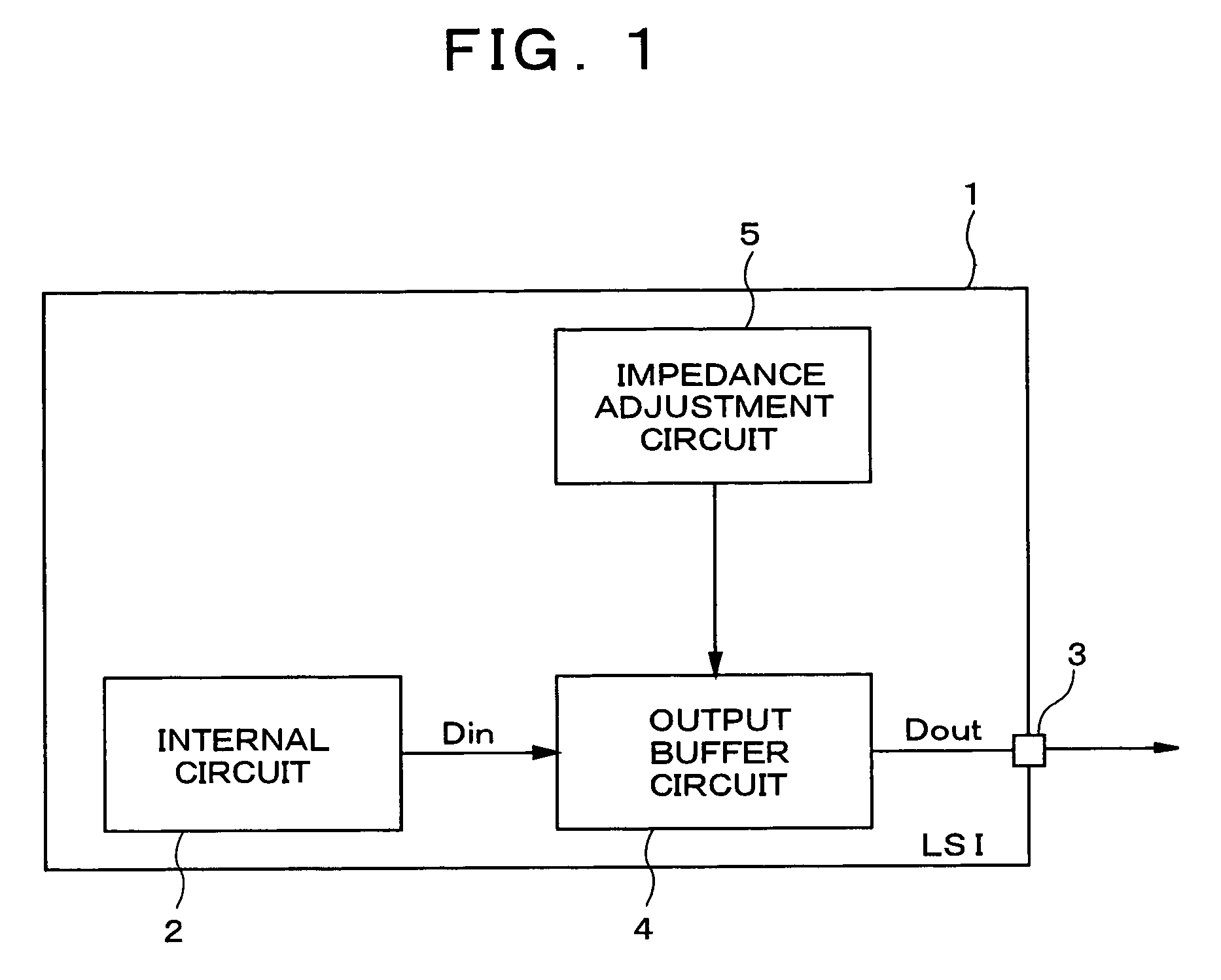
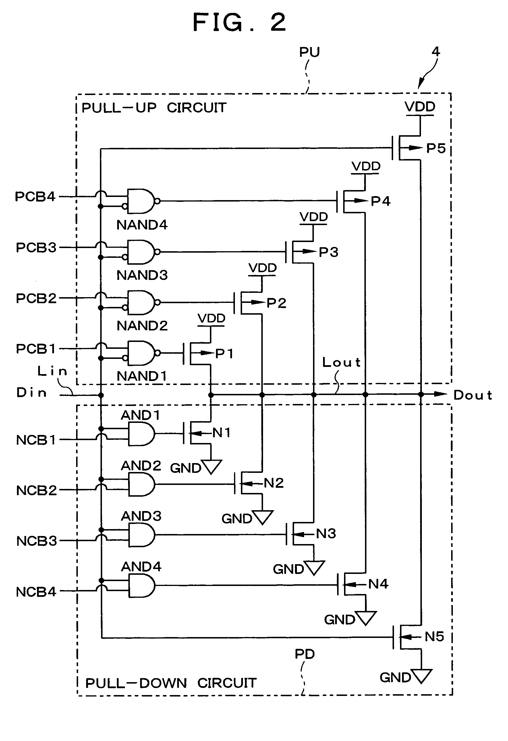
[0023]The embodiments of the present invention are described in detail below with reference to the attached diagrams. FIG.FIG. 1 is a block diagram showing the integrated circuit device of the embodiments of the present invention; FIG.FIG. 2 is a block diagram showing the output buffer shown in FIG.FIG. 1; FIG.FIG. 3 is a block diagram showing the impedance adjustment circuit shown in FIG.FIG. 1; FIG.FIG. 4 is a block diagram showing the NMOS array shown in FIG.FIG. 3; FIG.FIG. 5 is a block diagram showing the comparator circuit shown in FIG.FIG. 3; and FIG.FIG. 6 is a block diagram showing the PMOS array shown in FIG.FIG. 3.

[0024]As shown in FIG.FIG. 1, an internal circuit 2 that performs computing tasks, stores data, and carries out other types of signal processing is provided in LSI 1, which is the integrated circuit device of the present embodiment. Also provided is an output terminal 3 that outputs to the exterior of the LSI 1 signals that are output from the internal circuit 2...


PUM


Abstract

An NMOS impedance adjustment circuit has a comparator circuit for comparing with a reference electric potential VREFn a divided voltage potential Vin produced by an NMOS array and an external reference resistance. The NMOS array simulates the impedance of an output buffer circuit on the basis of the comparison result. The comparator circuit has three differential circuits. Three 2-input NAND gates and a single three-input NAND gate take the majority of output values of the differential circuits and output the result from the comparator circuit. A reduction of impedance adjustment precision caused by variability within the chip can thereby be inhibited.

Description

BACKGROUND OF THE INVENTION[0001]1. Field of the Invention[0002]The present invention relates to an impedance adjustment circuit for adjusting the impedance of an input and / or output buffer circuit, and to an integrated circuit device provided with the impedance adjustment circuit.[0003]2. Description of the Related Art[0004]In an interface that operates at high speed, the transmission lines between a transmitting circuit, receiving circuit, and LSI (Large Scale Integrated circuit) are handled as distributed constant circuits, and impedance matching is essential. If the impedance of the transmission lines and the impedance of the load circuit do not match, reflected wave is created at the boundary between the transmission lines and the load circuit, and the reflected wave causes the input buffer circuit to malfunction. A resistance is conventionally added to the output buffer circuit in order to match the impedance. This resistance is integrated into the LSI or is mounted outside of...

Claims


Application Information

Patent Timeline
Patent Type & Authority Patents(United States)
IPC IPC(8): H03K17/16
CPCH03K19/0005
Inventor OGURI, TAKASHI
Owner NEC CORP
Learn More