Antenna feed-tube-to-amplifier coupling

a technology of amplifier and feed tube, which is applied in the direction of antenna array, electrical apparatus, antennas, etc., can solve the problem of hardening the problem of feed tube to low-noise block down-converter, and achieve the effect of eliminating a source of tolerance accumulation, facilitating assembly and disassembly, and facilitating disassembly

Inactive Publication Date: 2008-10-28
KVH IND INC
View PDF3 Cites 12 Cited by
  • Summary
  • Abstract
  • Description
  • Claims
  • Application Information

AI Technical Summary

Benefits of technology

[0008]I have recognized, though, that the conventional mounting approach makes it harder than necessary to achieve a good fit of the feed tube to the low-noise block down-converter. By a subtle change in the assembly, I have devised a way of achieving a good fit more reliably and in a way that makes assembly and disassembly easier. Although I still secure the feed tube to the low-noise block down-converter (possibly through a bracket), I do not rely primarily on that connection for their support by the primary reflector. Instead, I secure one or the other of those two elements to the primary reflector independently of the feed tube's connection to the low-noise block down-converter, and I then secure the feed tube and low-noise block down-converter to each other. This makes assembly and disassembly easier because only two separate parts have to be handled at a time rather than three.

Problems solved by technology

I have recognized, though, that the conventional mounting approach makes it harder than necessary to achieve a good fit of the feed tube to the low-noise block down-converter.

Method used


Image

  • Antenna feed-tube-to-amplifier coupling
  • Antenna feed-tube-to-amplifier coupling
  • Antenna feed-tube-to-amplifier coupling

Examples


Embodiment Construction

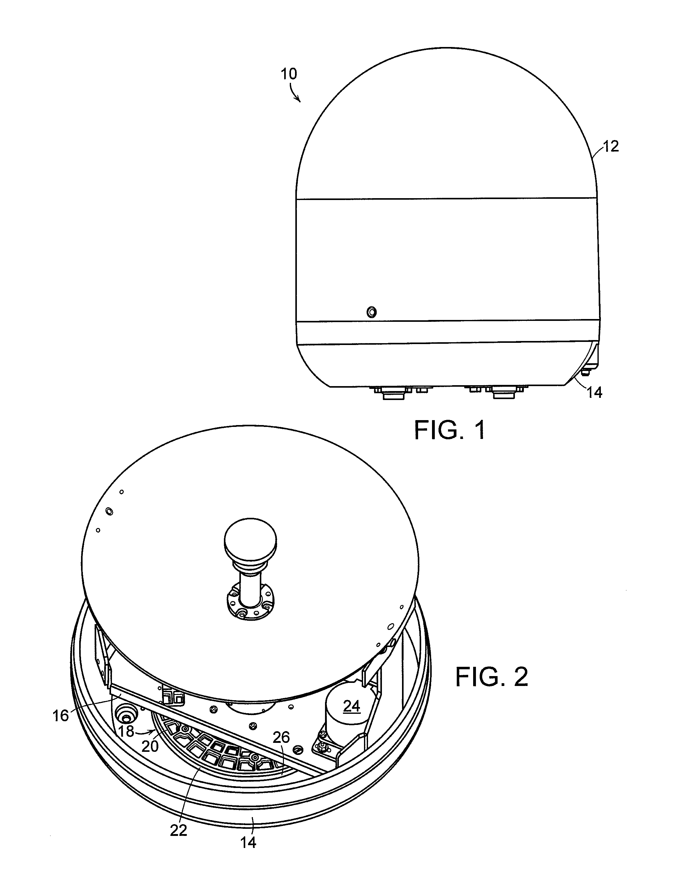
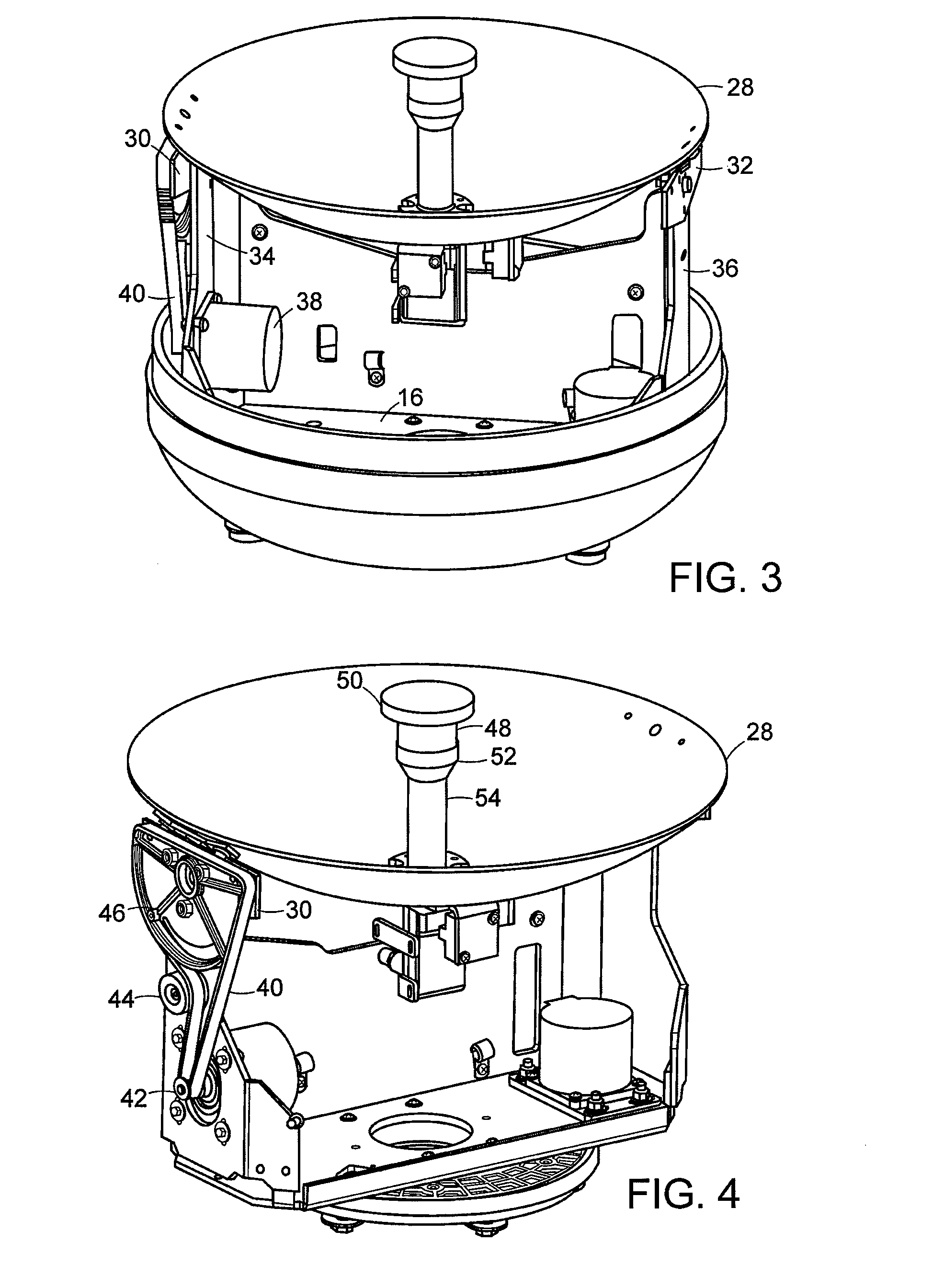
[0019]FIG. 1 depicts a typical satellite-antenna installation 10 of the type in which the present invention's teaching can be practiced. The antenna is protected from the elements by microwave-transparent radome 12 secured to a mounting base 14 adapted for mounting on a boat or other mobile platform. FIG. 2 depicts the assembly with the radome removed to reveal a rotating plate 16 journaled to the base 14 by a bearing assembly 18 whose inner race 20 is secured to that plate and whose outer race 22 is secured to the base 14. In response to drive current from control circuitry not shown, an azimuth servomotor 24 mounted on the rotating plate 16 controls the antenna orientation's azimuth component by driving a belt 26 trained about the stationary outer bearing race 22.

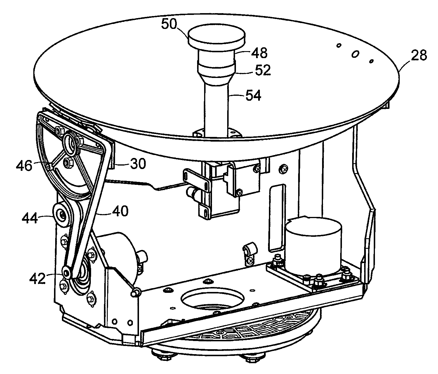
[0020]As FIG. 3 shows, the antenna's primary reflector 28 is secured to mounting brackets 30 and 32 pivotably mounted on respective uprights 34 and 36 that extend up from the rotating plate 16. In response to the control ...


PUM


Abstract

A first set of screws secures a Cassegrain-configuration microwave antenna's primary reflector to its low-noise block down-converter without additionally securing that reflector or the low-noise block down-converter to the antenna's feed tube, which a second set of screws separately secures to the low-noise block down-converter.

Description

BACKGROUND OF THE INVENTION[0001]1. Field of the Invention[0002]The present invention is directed to antennas for receiving satellite signals. It finds particular application in antennas for use on mobile platforms.[0003]2. Background Information[0004]A typical mobile satellite antenna has a stationary base mounted to its platform, such as a boat or recreational vehicle, and a satellite-following rotatable assembly is mounted on the base for two- or three-axis rotation with respect to the base. That rotatable assembly includes a primary reflector, a secondary shaped sub-reflector, and a low-noise block down-converter, and it may also include gyroscopes for providing sensor inputs to the rotatable assembly's orientation-control system.[0005]The reflectors are often arranged in Cassegrain configuration: microwaves from a small solid angle of sky are reflected by the paraboloidal primary reflector onto the smaller sub-reflector disposed in front the primary reflector. From the sub-refl...

Claims


Application Information

Patent Timeline
Patent Type & Authority Patents(United States)
IPC IPC(8): H01Q13/00H01Q19/10H01Q19/12H01Q21/00
CPCH01Q19/19
Inventor GRIFFITHS, GARY D.
Owner KVH IND INC
Why Eureka
Try Eureka