Method and apparatus for generating a cornering-corrected eLSD control signal

a control signal and cornering correction technology, applied in the direction of process and machine control, brake systems, instruments, etc., can solve the problems of unfavorable driver comfort or other undesired effects, inability to obtain accurate vehicle reference speed measurements in practice, and uneven turning speeds

Active Publication Date: 2008-10-28
GM GLOBAL TECH OPERATIONS LLC
View PDF3 Cites 22 Cited by
  • Summary
  • Abstract
  • Description
  • Claims
  • Application Information

AI Technical Summary

Benefits of technology

[0007]According to various exemplary embodiments, a new technique is provided for generating a slip control for an electronically-controlled limited slip differential (eLSD) that provides torque distribution to the turning wheels of a vehicle. In one embodiment, the method comprising the broad steps of obtaining indicia of a yaw rate of the vehicle, determining a target velocity difference for the turning wheels at least in part as a function of the yaw rate, and applying the slip control signal to the eLSD as a function of the determined target velocity difference. Because the target velocity differences are computed based upon yaw rate, wheel rotation speeds, road-wheel angles and / or other factors that can be readily determined, the need to measure a forward or lateral velocity of the vehicle is significantly diminished.

Problems solved by technology

Front and rear wheels similarly traverse different distances around the radius of the turn, thereby resulting in unequal turning speeds.
Challenges often arise, however, in that accurate vehicle reference speed measurements can be difficult to obtain in practice. eLSD computations that determine desired wheel speed based upon vehicle reference speeds, then, can occasionally produce driver discomfort or other undesired results.
In particular, vehicle investigations have shown that even slight differences in the determination of target wheel speed can result in improper clutch activation during low-speed, tight-turn applications such as parking-lot maneuvers and the like.

Method used


Image

  • Method and apparatus for generating a cornering-corrected eLSD control signal
  • Method and apparatus for generating a cornering-corrected eLSD control signal
  • Method and apparatus for generating a cornering-corrected eLSD control signal

Examples


Embodiment Construction

[0014]The following detailed description is merely exemplary in nature and is not intended to limit the invention or the application and uses of the invention. Furthermore, there is no intention to be bound by any expressed or implied theory presented in the preceding technical field, background, brief summary or the following detailed description.

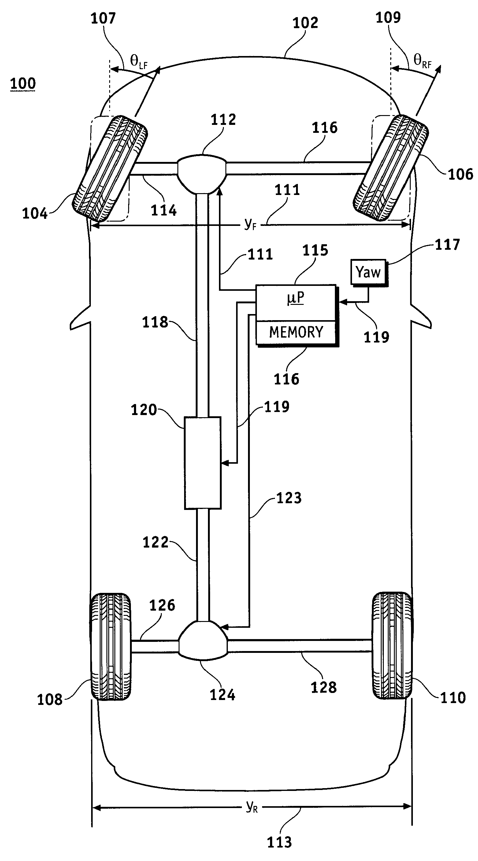
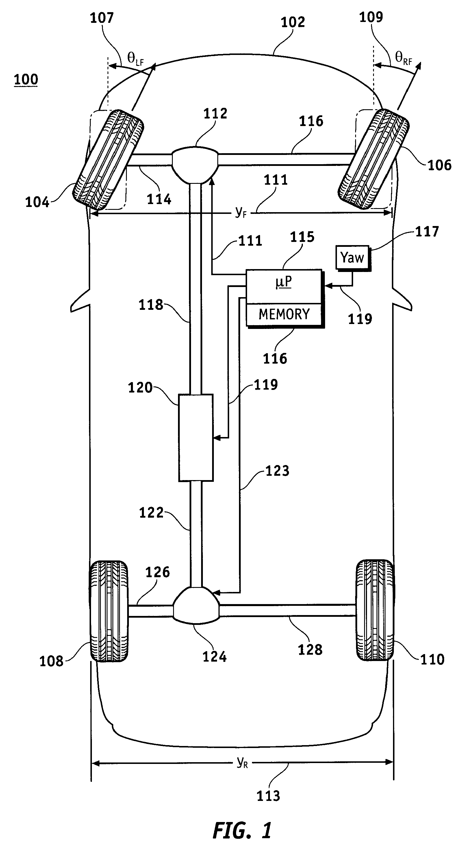
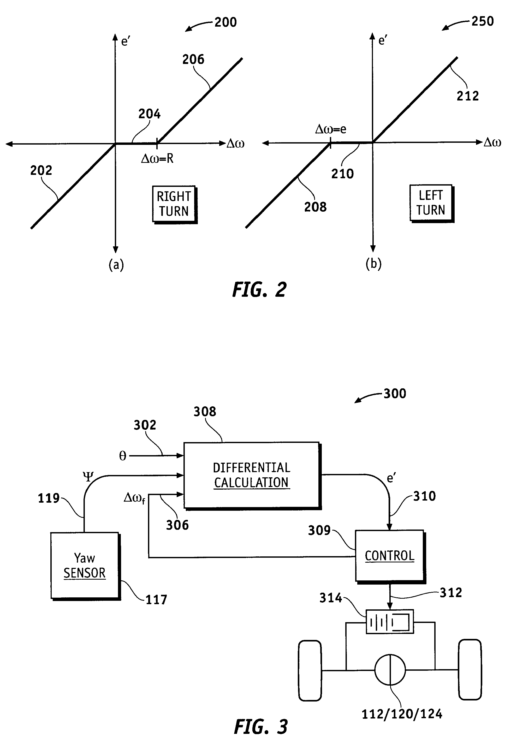
[0015]Various embodiments pertain to dynamic stability control of a turning vehicle. A slip control algorithm that is independent of vehicle reference speed is developed for an electronically-controlled limited slip differential (eLSD). The slip control algorithm is based on the difference between a calculated target delta-velocity and the measured difference in wheel speeds. The target delta-velocity can be derived from measured road-wheel angle and vehicle yaw rate information, and is therefore independent of vehicle reference speed, which can be difficult to measure in practice. In various embodiments, a difference term computed from th...


PUM


Abstract

Methods and apparatus are provided for generating a slip control for an active driveline device (such as an electronic limited slip differential (eLSD)) that corrects for longitudinal tire slip in the turning wheels of a vehicle. Indicia of a yaw rate of the vehicle are obtained by the eLSD, which then determining a target velocity difference for the turning wheels based at least in upon the yaw rate, along with other factors such as difference in wheel rotation speed or the wheel-road angle of the vehicle. Using these measured parameters, a slip control signal can be applied to the eLSD as a function of the determined target velocity difference.

Description

TECHNICAL FIELD[0001]The present invention generally relates to control of a limited slip differential in a vehicle, and more particularly relates to the generation of a slip control signal for an electronically-controlled limited slip differential for a vehicle.BACKGROUND OF THE INVENTION[0002]When a conventional vehicle such as a passenger automobile or truck turns, each of the four wheels on the vehicle can rotate at different speeds. The wheels on the side of the vehicle facing into the turn, for example, typically spin at a slower rate than those on the outside of the turn due to the shorter distance traversed by the inside wheels. Front and rear wheels similarly traverse different distances around the radius of the turn, thereby resulting in unequal turning speeds. For non-driven wheels (e.g., the front wheels in a rear-wheel-drive automobile), the difference in speed is easily accommodated. For wheels that are driven with engine torque, however, the wheels must be mechanicall...

Claims


Application Information

Patent Timeline
Patent Type & Authority Patents(United States)
IPC IPC(8): G06D1/00
CPCB60K17/3462B60K23/0808B60K28/165B60T8/17555B60T8/1769B60W10/14B60W10/16B60K17/30B60T2201/14B60T2201/16B60W2050/0041B60W2520/14B60W2520/28B60W2530/20Y02T10/56Y02T10/40
Inventor VILLELLA, MATTHEW G.GAFFNEY, EDMUND F.
Owner GM GLOBAL TECH OPERATIONS LLC
Why Eureka
Try Eureka