Fuel line check valve

a check valve and fuel line technology, applied in the field of fuel systems, can solve the problems of fuel leakage in automotive fuel systems, fuel leakage may occur, fuel leakage is particularly exacerbated, etc., and achieve the effect of reducing fuel leakage and evaporative emissions

Active Publication Date: 2008-11-04
ROBERT BOSCH CORP +1
View PDF41 Cites 45 Cited by
  • Summary
  • Abstract
  • Description
  • Claims
  • Application Information

AI Technical Summary

Benefits of technology

[0004]Relieving fuel system pressure during such diurnal temperature cycles can reduce fuel leakage and evaporative emissions from the fuel system.

Problems solved by technology

Fuel leakage in automotive fuel systems may occur during periods of non-operation of the automobile.
Such leakage may occur through fuel injectors, or through various components in the fuel system by permeation, because most modern fuel injection systems remain pressurized after the automobile is turned off.
Fuel leakage is particularly exacerbated by diurnal temperature cycles.
In conjunction with this temperature rise, the pressure in the fuel system of a non-operating automobile also increases, often resulting in leakage through the fuel injectors and other fuel system components.
This temperature cycle repeats each day, thus often resulting in a repeated cycle of fuel leakage and evaporative emissions.

Method used


Image

  • Fuel line check valve
  • Fuel line check valve
  • Fuel line check valve

Examples


Embodiment Construction

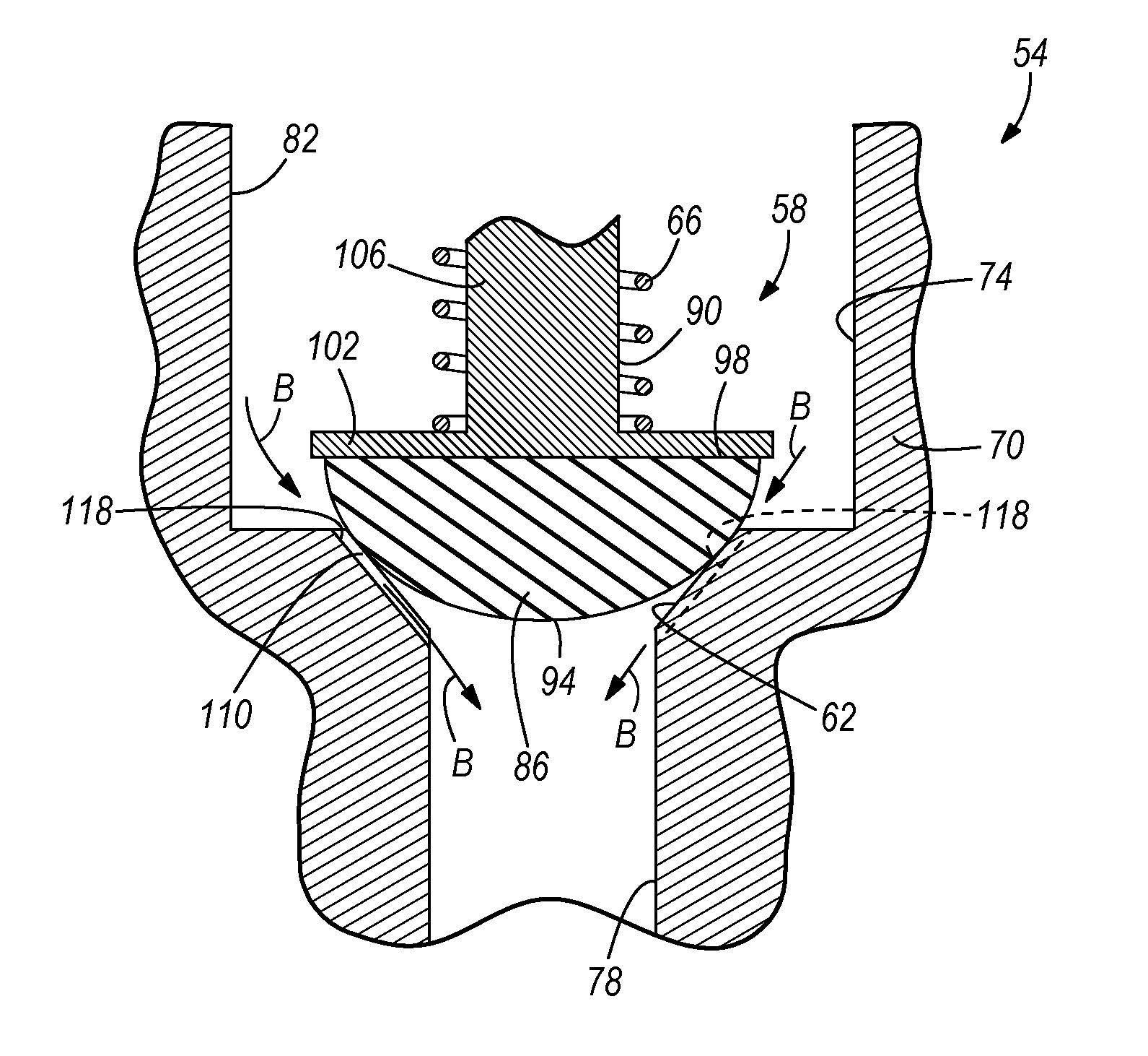
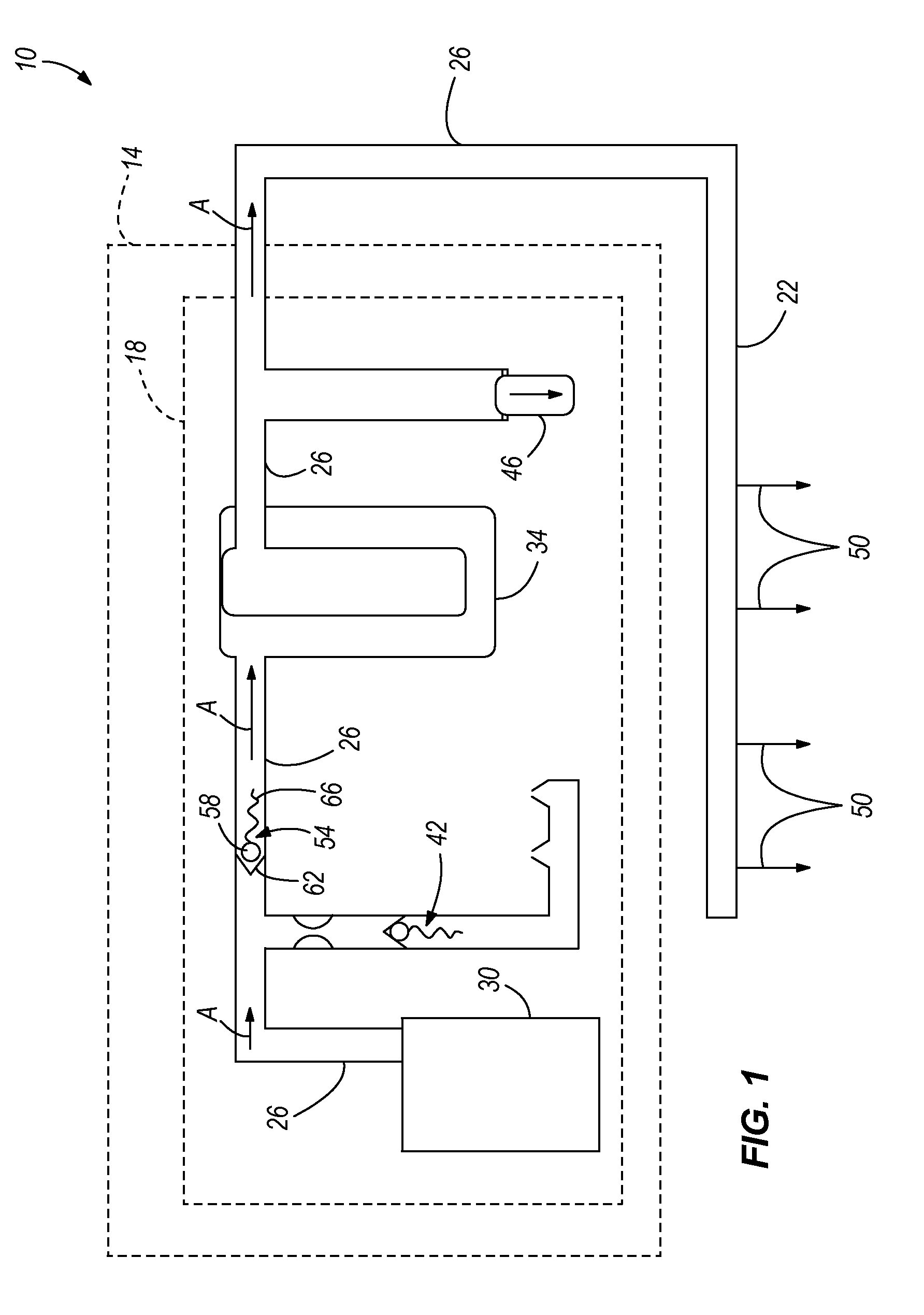
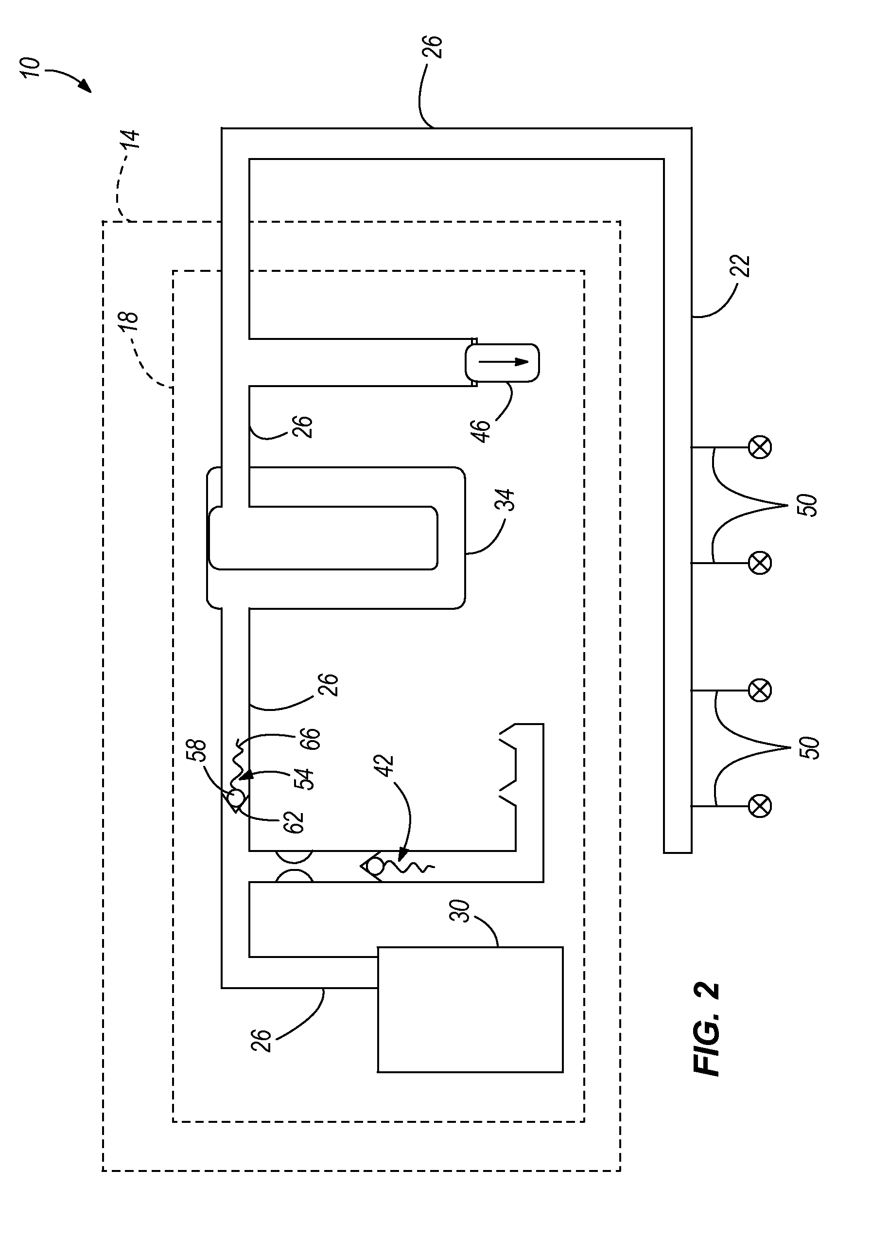
[0024]FIGS. 1-3 schematically illustrate a fuel system 10 including a fuel tank 14, a fuel pump module 18 positioned in the fuel tank 14, a fuel rail 22 coupled to an engine, and a fuel line 26 fluidly communicating the fuel pump module 18 and the fuel rail 22. The fuel pump module 18 includes a fuel pump 30 and a fuel filter 34 in fluid communication with the fuel line 26, a portion of which is contained within the fuel pump module 18. The fuel pump module 18 also includes a rollover check valve 42 and a fuel pressure relief valve 46 in fluid communication with the fuel line 26.

[0025]In a conventional manner, the fuel pump 30, during operation, discharges pressurized fuel at an operating pressure through the portion of the fuel line 26 between the fuel pump 30 and the fuel filter 34. Fuel then flows through the fuel filter 34 and through the rest of the fuel line 26 to fill the fuel rail 22 with pressurized fuel. Depending on the engine with which the fuel system 10 is utilized, th...


PUM


Abstract

A check valve includes a body defining a passageway through which fuel flows in a first fuel-flow direction during pump operation. The check valve also includes a seat, a seal member, and a biasing member biasing the seal member toward the seat. The seal member is movable between a first seated position in which the seal member is engaged with the seat and the pressure in the fuel rail is substantially equal to the operating pressure, and a second seated position in which the seal member is engaged with the seat and a residual pressure in the fuel rail is substantially less than the operating pressure. The seal member and the seat define a leak path between the fuel pump and the fuel rail permitting fuel to flow in a second fuel-flow direction opposite the first fuel-flow direction when the seal member is in the second seated position.

Description

FIELD OF THE INVENTION[0001]The present invention relates to fuel systems, and more particularly to fuel pressure relief valves in fuel systems.BACKGROUND OF THE INVENTION[0002]Fuel leakage in automotive fuel systems may occur during periods of non-operation of the automobile. Such leakage may occur through fuel injectors, or through various components in the fuel system by permeation, because most modern fuel injection systems remain pressurized after the automobile is turned off. Maintaining fuel pressure in the fuel system after an automobile is turned off is a common practice of automotive manufacturers to maintain the readiness of the fuel system for quick engine restarting (i.e., “hot-restarts”), and also to minimize emissions during restart and avoid delays in restarting.[0003]Fuel leakage is particularly exacerbated by diurnal temperature cycles. During a typical day, the temperature rises to a peak during the middle of the day. In conjunction with this temperature rise, the...

Claims


Application Information

Patent Timeline
Patent Type & Authority Patents(United States)
IPC IPC(8): F02M69/00F02M37/20
CPCF02D33/006F02M37/0029F02M37/20F16K15/044F16K15/063F16K15/14F16K25/005F02M69/465
Inventor FISHER, PAULMASON, PAULPANGBURN, DANIEL
Owner ROBERT BOSCH CORP
Why Eureka
Try Eureka