Fuel pump

a technology of fuel pump and pump body, which is applied in the direction of liquid fuel engines, machines/engines, mechanical equipment, etc., can solve the problems of high manufacturing cost, difficult to realize both the reduction of sliding resistance and fuel leakage reduction at a low manufacturing cost and with good stability, and achieve high degree of precision. , the effect of increasing manufacturing cos

Inactive Publication Date: 2013-09-03
AISAN IND CO LTD
View PDF27 Cites 1 Cited by
  • Summary
  • Abstract
  • Description
  • Claims
  • Application Information

AI Technical Summary

Benefits of technology

[0008]In the above-described fuel pump, because a plurality of concave portions is formed in the inner surface of the casing, it is necessary to perform complex cutting of the casing. Moreover, because a high degree of precision is required for this cutting operation, manufacturing cost increases. Moreover, where the concave portions are formed by mechanical processing such as cutting, there is a variation in the shape of concave portions. As a result, there is a variation in pump efficiency. For these reasons, with the above-described technology, it is difficult to realize both the reduction in fuel leakage and the reduction in sliding resistance at a low manufacturing cost and with good stability.
[0009]It is one object of the present teachings to provide a fuel pump that can be manufactured at a low cost and in which both the reduction of fuel leakage and the reduction in sliding resistance can be realized with good stability.
[0011]In this fuel pump, the seal portion that seals leakage of the fuel comprises one layer or a plurality of thin films. The formation of a thin film is easier and processing accuracy is higher than in the case of shaping by mechanical processing such as cutting. Thus, even if a seal portion has a complex shape, the seal portion can be manufactured at a low cost by using a thin film. Furthermore, a seal portion using a thin film has high accuracy. As a result, both the reduction in fuel leakage and the reduction in sliding resistance can be realized at a low manufacturing cost and with good stability.

Problems solved by technology

Moreover, because a high degree of precision is required for this cutting operation, manufacturing cost increases.
For these reasons, with the above-described technology, it is difficult to realize both the reduction in fuel leakage and the reduction in sliding resistance at a low manufacturing cost and with good stability.

Method used


Image

  • Fuel pump
  • Fuel pump
  • Fuel pump

Examples


embodiment 1

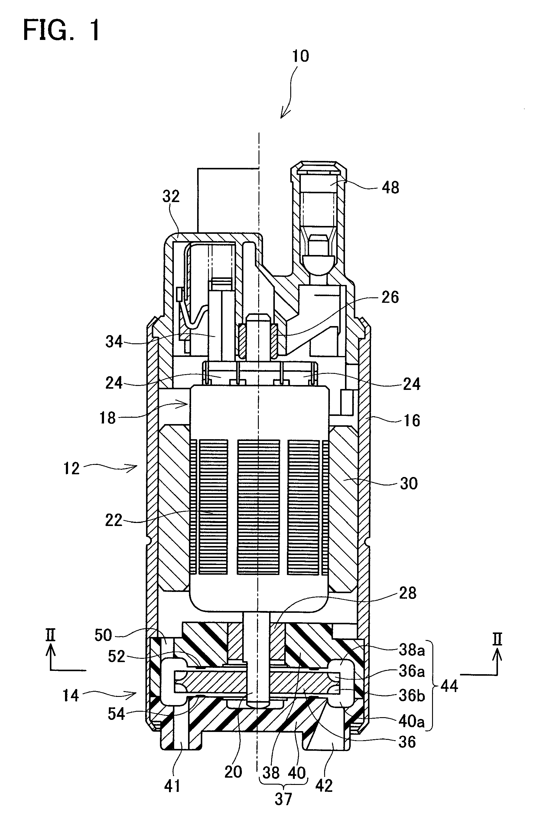
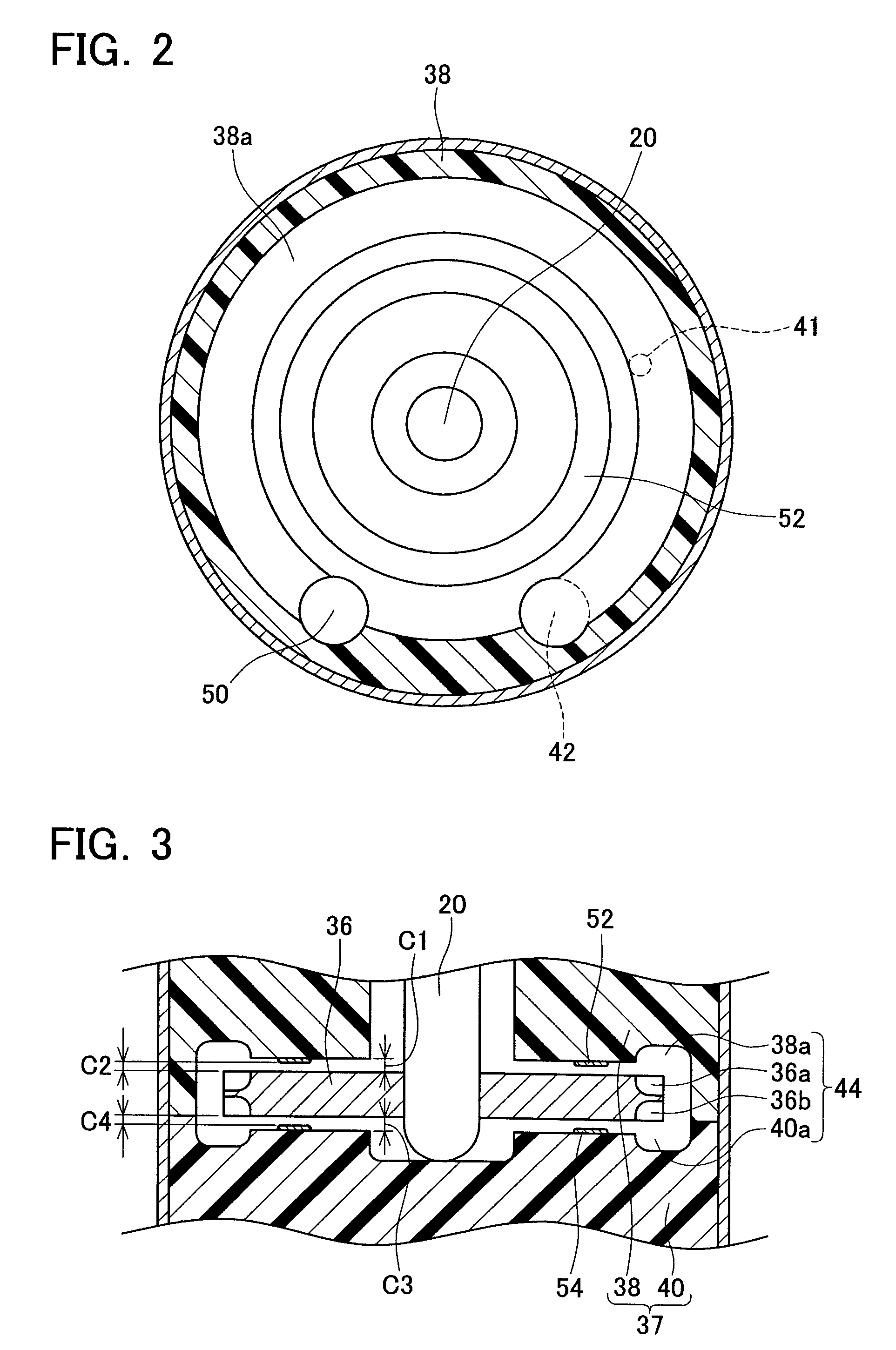
[0041]A first embodiment of the present teachings will be explained below. A fuel pump of the present embodiment is a fuel pump for an automobile. The fuel pump is disposed within a fuel tank and serves to supply fuel to the automobile engine. As shown in FIG. 1, a fuel pump 10 comprises a motor unit 12 and a pump unit 14 accommodated in a housing 16. The motor unit 12 has a rotor 18. The rotor 18 has a shaft 20, a laminated iron core 22 that is fixed to the shaft 20, a coil (not shown in the figure) that is wound about the laminated iron core 22, and a commutator 24 connected to the ends of the coil. The shaft 20 is supported by bearings 26, 28 so that it can rotate with respect to the housing 16. A permanent magnet 30 is fixed inside the housing 16 so as to surround the rotor 18. Terminals (not shown in the figure) are provided at a top cover 32 attached to the upper portion of the housing 16. The terminals are electrically connected to the rotor 18. When electric current is suppl...

embodiment 2

[0049]A second embodiment of the present teachings will be explained below. The fuel pump of the second embodiment is a partial modification of the fuel pump of the first embodiment. Accordingly, only the difference between the fuel pump of this embodiment and that of the first embodiment will be explained to avoid redundant explanation. Furthermore, components that are common for the fuel pump of the second embodiment and the fuel pump of the first embodiment will be denoted by similar reference symbols. The same is true for the below-described third to eleventh embodiments.

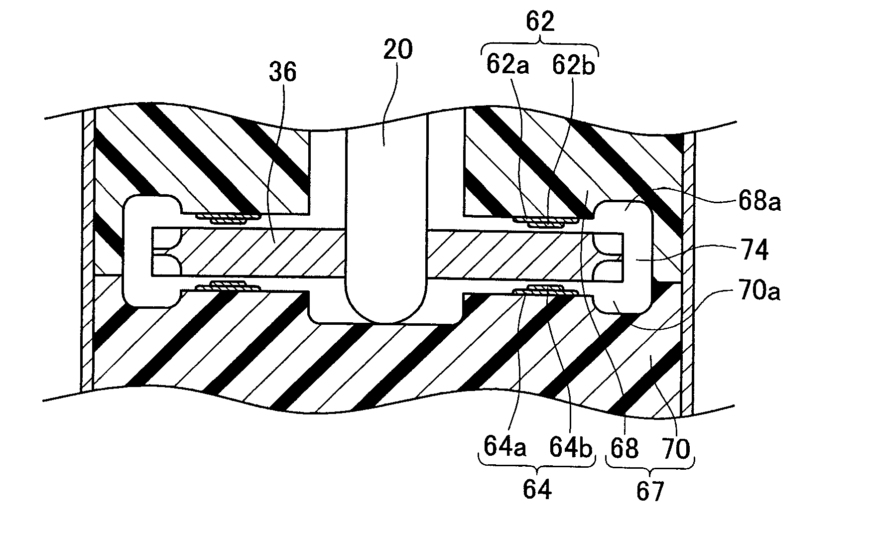
[0050]As shown in FIG. 4 and FIG. 5, a seal layer 62 is formed on a surface of a pump cover 68 that faces an upper surface of an impeller 36. Similarly to the first embodiment, the seal layer 62 is a thin film made from a synthetic resin. The seal layer 62 can be formed by the same method as used in the first embodiment. The seal layer 62 is formed by laminating a lower layer 62a and an upper layer 62b. A width ...

embodiment 3

[0053]A third embodiment of the present teachings will be explained below. As shown in FIG. 6 and FIG. 7, a seal layer 82 is formed on a surface of a pump cover 88 that faces an upper surface of an impeller 36. The seal layer 82 is a thin film made from a synthetic resin. The seal layer 82 is formed by the same method as in the above-described embodiments. The seal layer 82 is formed to have an almost ring shape and is formed between a discharge hole 50 and an upstream end of the groove 88a (i.e., an intake hole 42). Thus, the seal layer 82 is formed also in an area 82c located between the discharge hole 50 and the intake hole 42. The outer end of the seal layer 82 extends close to a circle to which a central line in the radial direction of a groove 88a can be extended in the circumferential direction. As shown in FIG. 7, the diameter of the circle serving as a central line in the radial direction of the groove 88a almost matches the outer diameter of the impeller 36. Further, the s...


PUM


Abstract

A fuel pump is provided with a casing and a substantially disk-shaped impeller that can rotate within the casing. A group of concavities is formed in each surface of the impeller. The concavities forming the group are arranged in concentric circles with respect to the rotation axis of the impeller. A first groove is formed in a first inner surface of the casing and extends from an upstream end to a downstream end in an area that faces one group of concavities. A second groove is formed in a second inner surface of the casing and extends from an upstream end to a downstream end in an area that faces the other group of concavities. A seal portion is formed in at least one of the first and second inner surfaces of the casing and formed by one layer or a plurality of layers of thin film.

Description

CROSS-REFERENCE TO RELATED APPLICATION[0001]This application claims priority to Japanese Patent Application No. 2006-251619 filed on Sep. 15, 2006, the contents of which are hereby incorporated by reference into the present application.BACKGROUND OF THE INVENTION[0002]1. Field of the Invention[0003]The present invention relates to a fuel pump that draws in a fuel, increases the pressure thereof, and discharges the pressurized fuel.[0004]2. Description of the Related Art[0005]A known fuel pump generally comprises a casing and an impeller rotatably disposed within the casing. A first group of concavities is formed in a lower surface of the impeller. A second group of concavities is formed in an upper surface. The concavities are repeated in a circumferential direction. A first groove is formed in a first inner surface of the casing in an area that faces the first group of concavities of the impeller. A second groove is formed in a second inner surface of the casing in an area that fac...

Claims


Application Information

Patent Timeline
Patent Type & Authority Patents(United States)
IPC IPC(8): F04D29/08F04D29/12
CPCF04D5/002F04D29/086F04D29/165F04D29/188
Inventor IKEYA, MASAKIMURAISHI, AKIO
Owner AISAN IND CO LTD
Why Eureka
Try Eureka