Magnetized fuel injector valve and valve seat

a fuel injector and magnetized technology, which is applied in the direction of valve operating means/release devices, electric control, machines/engines, etc., can solve the problems of fuel drip into the engine, fueling control problems, fueling control failures, etc., to reduce the speed of the valve mechanism, reduce the noise of ticking and stress on the fuel injector components

Active Publication Date: 2015-08-25
FORD GLOBAL TECH LLC
View PDF6 Cites 0 Cited by
  • Summary
  • Abstract
  • Description
  • Claims
  • Application Information

AI Technical Summary

Benefits of technology

[0003]However, the inventors herein have recognized that the moving parts in a fuel injector, such as those described above, may bounce against each other during motion. This bouncing may lead to degradation in components and operation of the fuel injector. For example, the bouncing may lead to fuel leaking through the injector causing fuel to drip into the engine. The dripped fuel may increase particulate matter (PM) formation during engine combustion, for example. Further, the leaking fuel is unmetered and may cause fueling control issues. The leaking fuel may also lead to deposit formation on the injector tip, thereby changing the injector flow transfer function and spray quality, for example. Further, due to the bouncing of the injector, there may be a limit on how quickly the injector can be opened for subsequent injections. Further still, the bouncing may increased injector tick noise and wear on injector components.
[0005]In this way, since at least one of the valve mechanism and the valve mechanism seat is permanently magnetized, a magnetic force may attract the valve mechanism to the valve mechanism seat which may reduce bouncing when the valve mechanism engages with the valve seat. This reduction in bouncing may reduce undesired residual fuel leaking when the injector is closed leading to a reduction in the formation of particulate matter and particulate emissions. Further, an accuracy of fuel metering may be increased due to a decrease in fuel leakage. For example, with reduced injector bounce, injector closing times may be reduced and injector response times may be increased. Further still, fuel velocity and inertia may be increased so that the time between subsequent injections may be reduced, which may, for example, increase split injection performance.
[0007]In this way, for example, a polarity of the injector driver may be reversed to oppose the valve mechanism to seat attraction, thereby reducing the speed of the valve mechanism near closing and creating a soft landing effect. This may reduce tick noise and stress on fuel injector components. For example, initial spring forces on the valve mechanism and wear on a contact surface between the valve mechanism and the seat may be reduced.

Problems solved by technology

This bouncing may lead to degradation in components and operation of the fuel injector.
For example, the bouncing may lead to fuel leaking through the injector causing fuel to drip into the engine.
Further, the leaking fuel is unmetered and may cause fueling control issues.
The leaking fuel may also lead to deposit formation on the injector tip, thereby changing the injector flow transfer function and spray quality, for example.
Further, due to the bouncing of the injector, there may be a limit on how quickly the injector can be opened for subsequent injections.
Further still, the bouncing may increased injector tick noise and wear on injector components.

Method used


Image

  • Magnetized fuel injector valve and valve seat
  • Magnetized fuel injector valve and valve seat
  • Magnetized fuel injector valve and valve seat

Examples


Embodiment Construction

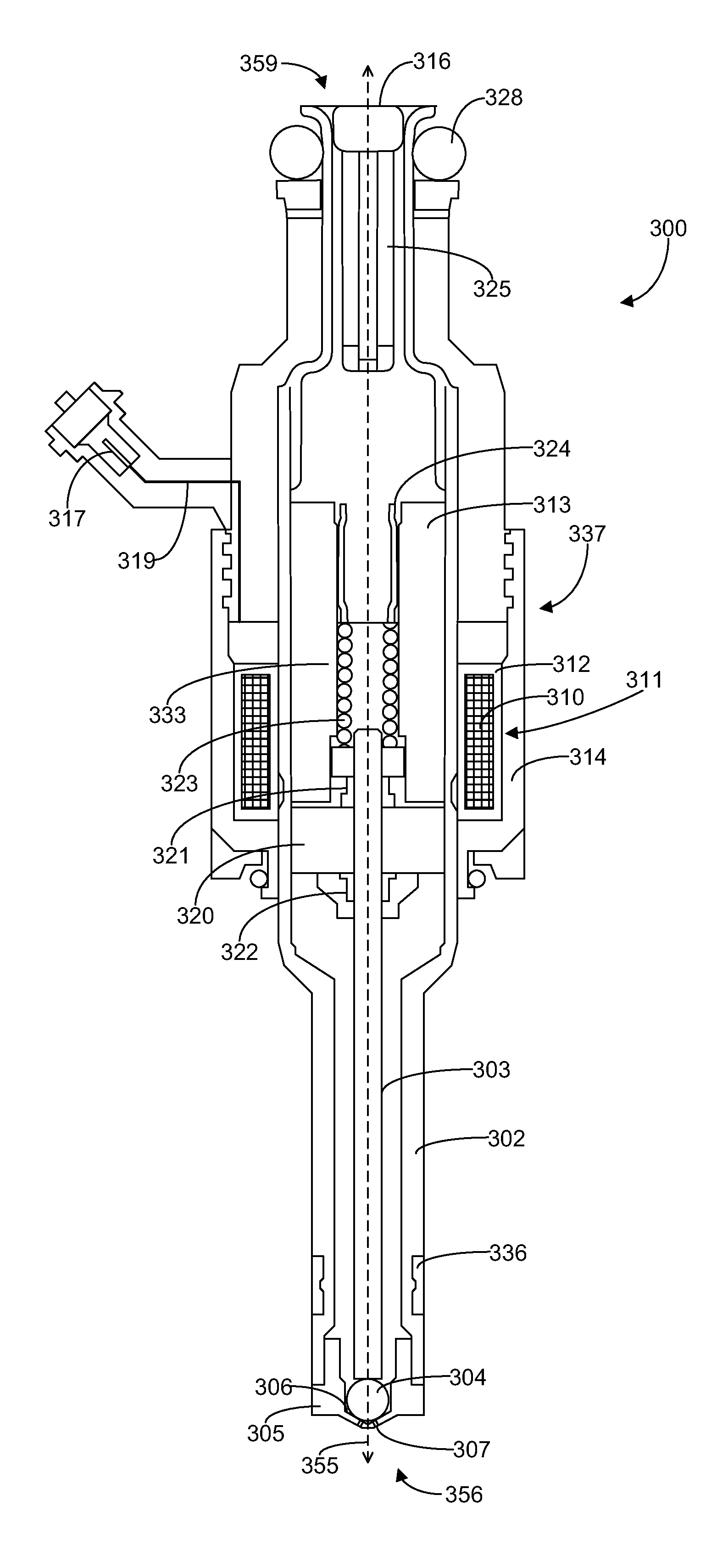
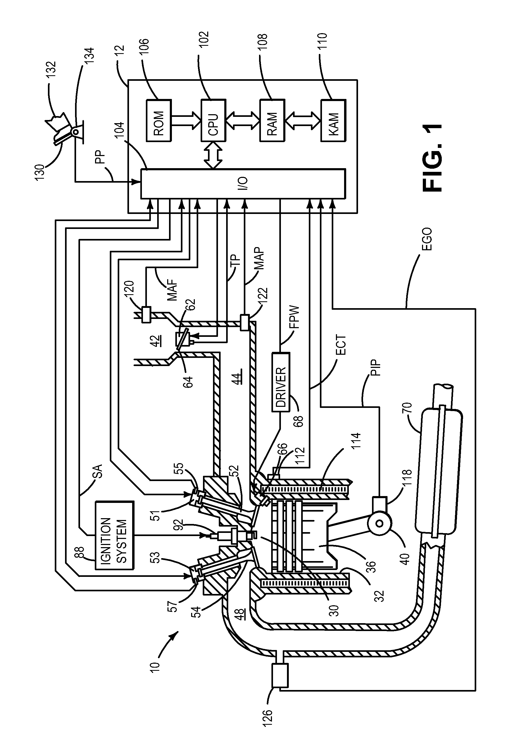
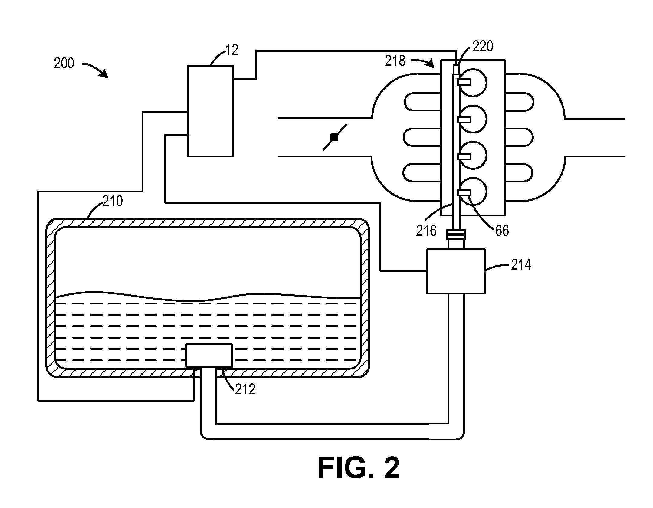
[0014]The present disclosure is directed to systems and methods for a permanently magnetized valve mechanism and / or valve mechanism seat of a fuel injector for a combustion engine, such as the example engine shown in FIG. 1. Such fuel injectors may be included in a fuel system, such as the example fuel system shown in FIG. 2, to inject fuel from a fuel source into the combustion engine. As remarked above, fuel injectors, such as the example fuel injector shown in FIG. 3, have moving parts that control fuel flow through the injector. For example, a fuel injector may include a valve mechanism which engages with a valve mechanism seat to close off fuel delivery to an engine. A valve actuator, e.g., an electromagnetic valve actuator, may actuate the valve mechanism to lift it from the valve mechanism seat so that fuel may be delivered to the engine during fuel injection events. In order to reduce bouncing and wear of components and operation of a fuel injector, some components of the fu...


PUM


Abstract

Systems and methods for a permanently magnetized valve mechanism and / or valve mechanism seat for a fuel injector are disclosed. In one example approach, a fuel injector comprises a valve mechanism and a valve mechanism seat, wherein at least one of the valve mechanism and the valve mechanism seat is permanently magnetized; an injector driver circuit for actuating the valve mechanism; and a spring biasing the valve mechanism in a closed position against the valve mechanism seat. For example, a first amount of current may be supplied in a first direction to the injector driver to lift a permanently magnetized injector valve mechanism from the injector valve mechanism seat, and a second amount of current may be supplied in a second direction to the injector driver to close the permanently magnetized injector valve mechanism onto the injector valve mechanism seat.

Description

BACKGROUND AND SUMMARY[0001]Fuel injectors may be used to inject fuel from a fuel source into combustion engines. For example, fuel injectors may inject fuel directly into combustion chambers of an engine in what is known as direct injection or fuel injectors may inject fuel into an intake passage of an engine in what is known as port injection.[0002]Fuel injectors have moving parts that control fuel flow through the injector. For example, a fuel injector may include a valve mechanism which engages with a valve mechanism seat to close off fuel delivery to an engine. A valve actuator, e.g., an electromagnetic valve actuator, may actuate the valve mechanism to lift it from the valve mechanism seat so that fuel may be delivered to the engine during fuel injection events.[0003]However, the inventors herein have recognized that the moving parts in a fuel injector, such as those described above, may bounce against each other during motion. This bouncing may lead to degradation in componen...

Claims


Application Information

Patent Timeline
Patent Type & Authority Patents(United States)
IPC IPC(8): F02M51/06F16K31/08F02D41/20
CPCF02M51/0689F02D41/20F02D2041/2037F02D2041/2048
Inventor BASMAJI, JOSEPHSURNILLA, GOPICHANDRAGANDHI, ANAND
Owner FORD GLOBAL TECH LLC
Why Eureka
Try Eureka