Fuel system and method for reducing fuel leakage from a fuel system

a fuel system and fuel system technology, applied in the field of fuel systems, can solve the problems of uncontrollable leakage further out of the fuel system, low viscosity fuel such as dme, may leak, and fuel vapour leakage to the ambient may occur anyway, so as to achieve less complex and more cost-effective fuel pumps.

Active Publication Date: 2017-07-18
VOLVO LASTVAGNAR AB
View PDF28 Cites 1 Cited by
  • Summary
  • Abstract
  • Description
  • Claims
  • Application Information

AI Technical Summary

Benefits of technology

[0001]This invention relates, according to an aspect thereof, to a fuel system for supplying pressurised fuel, in particular dimethyl ether (DME) or a blend thereof, to an internal combustion engine. The fuel system comprises a fuel pump, which has a pumping mechanism arranged partly in a housing containing lube oil, and a drain line connected to said housing and suitable for draining at least fuel vapour from an interior of said housing. An aspect of the invention also relates to a method for reducing fuel leakage from a corresponding fuel system.

Problems solved by technology

In particular low viscosity fuel, such as DME, may leak past the high pressure seal of the pumping element into the camshaft chamber of the fuel pump, from where it may uncontrollably leak further out from the fuel system.
Fuel vapour leakage to the ambient may however occur anyway to a limited extent in certain operating conditions.
As described in connection with the prior art, fuel vapour leakage may occur to a limited extent in certain operating conditions despite the leak gas pipe, in particular in an engine non-running state when no negative pressure is generated by the power cylinders of the combustion engine.
However, sealing material compatible with in particular low viscosity fuels such as DME are expensive and may have lower durability than conventional seals, which are normally used for this sealing application.
Moreover, since the drain valve can no longer be used for closing the lube oil return line, an additional valve is provided in the return line for this purpose, namely the lube oil return valve.
This design may thus possibly omit a lube oil separator installed in the drain line.
Otherwise, no efficient lube oil fill level, control may be realised.

Method used


Image

  • Fuel system and method for reducing fuel leakage from a fuel system
  • Fuel system and method for reducing fuel leakage from a fuel system
  • Fuel system and method for reducing fuel leakage from a fuel system

Examples


first embodiment

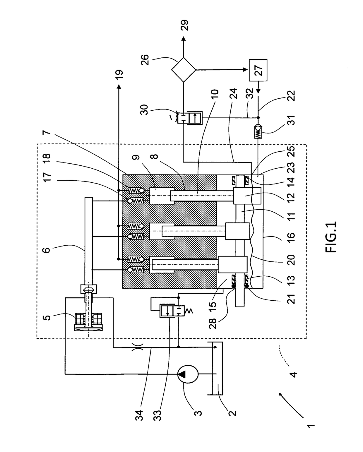
[0032]FIG. 1 shows the fuel system 1 according to an aspect of the invention. The fuel system 1 is particularly suitable for supplying pressurised low viscosity fuel, such as dimethyl ether (DME) or a blend thereof, to an internal combustion engine, but the fuel system 1 is equally suitable for conventional fuel, such as diesel. The fuel system 1 comprises a fuel tank 2 from which a low pressure fuel pump 3 draws fuel and supplies it to a high pressure fuel pump 4. The high pressure fuel pump 4, hereinafter simply referred to as fuel pump 4, is in many ways formed as a conventional fuel pump 4 that comprises an inlet metering valve 5 receiving fuel from the low pressure fuel pump 3. The inlet metering valve 5 controls the amount of fuel that is allowed to enter a suction channel 6, which functions as a fuel source for a pumping unit.

[0033]The pumping unit comprises a fuel pump block 7 with a plurality of pumping chambers 9 and cylinders 8, each cylinder 8 receiving a pumping element...

third embodiment

[0049]FIG. 3 shows schematically an aspect of the invention, displaying an alternative lube oil return arrangement. The difference with respect to the previous embodiment is only in that a separate lube oil return valve 36 is installed in a separate lube oil return line 35. The lube oil return valve 36 being capable of opening and closing the lube oil return line 35, which connects the housing 16 with the low pressure lube oil reservoir 27. The function of the fuel system have not changed, and the lube oil return valve 36 is configured to be open during an engine running state, and closed in the engine non-running state. The difference with respect to the previous embodiment is merely that the drain line 24 and drain valve 30 are adapted for handling of fuel vapour, whilst the separate lube oil return line 35 and return valve 36 are adapted for handling of lube oil. The lube oil separator 26 may thus no longer be required.

[0050]The advantage of the design of the third embodiment sho...

fifth embodiment

[0055]FIG. 5 shows schematically an aspect of the invention displaying yet another alternative lube oil return arrangement. Here, the lube oil return line 35 is connected to a lower section of said housing 16, adjacent the bottom of the housing 16, and the lube oil fill level 20 is controlled by an electronic lube oil level controller 40, which controls flow through the lube oil return valve 36 based on input from an oil detection sensor 42. This lube oil return arrangement more easily allows an adaptable lube oil fill level 20, and the opening and closing timing of the lube oil return valve is independent from the lube oil pressure within lube oil supply line 22.

[0056]A safety means 41, 43 is also provided in the form of an electronic control unit 41 and an electronically controlled safety valve 43, which is arranged to control the flow of lube oil from the lube oil reservoir 27 to the fuel system 1. The safety means 41, 43 is also arranged to be able to close the drain, line 24 to...


PUM


Abstract

A fuel system is provided for supplying pressurized fuel, in particular dimethyl ether (DME) or a blend thereof, to an internal combustion engine. The fuel system includes a fuel pump, which has a pumping mechanism arranged partly in a housing containing lube oil, a drain line connected to the housing and suitable for draining at least fuel vapor from an interior of the housing, a lube oil supply line connected to the housing, a lube oil supply valve installed in the lube oil supply line, a seal installed between the pumping mechanism and the housing for preventing at least lube oil leakage to the outside of the housing, and a drain valve installed in the drain line, wherein both the drain valve and lube oil supply valve are controlled to be closed during an engine non-running state for preventing fuel vapor leakage from the housing.

Description

BACKGROUND AND SUMMARY[0001]This invention relates, according to an aspect thereof, to a fuel system for supplying pressurised fuel, in particular dimethyl ether (DME) or a blend thereof, to an internal combustion engine. The fuel system comprises a fuel pump, which has a pumping mechanism arranged partly in a housing containing lube oil, and a drain line connected to said housing and suitable for draining at least fuel vapour from an interior of said housing. An aspect of the invention also relates to a method for reducing fuel leakage from a corresponding fuel system.[0002]The fuel system is particularly suitable for supplying low viscosity fuel, such as DME, to a diesel engine of a heavy truck.[0003]In particular low viscosity fuel, such as DME, may leak past the high pressure seal of the pumping element into the camshaft chamber of the fuel pump, from where it may uncontrollably leak further out from the fuel system. One prior art solution to this problem is known from JP1028102...

Claims


Application Information

Patent Timeline
Patent Type & Authority Patents(United States)
IPC IPC(8): F02M69/02F02M59/44F02M25/06
CPCF02M69/02F02M59/44F02M25/06F01M2011/021F01M11/02
Inventor YUDANOV, SERGI
Owner VOLVO LASTVAGNAR AB
Why Eureka
Try Eureka