RF field mapping for magnetic resonance imaging

a magnetic resonance imaging and rf field technology, applied in the field of magnetic resonance imaging, can solve the problems of inapplicability of methods, inability to apply, and limitations of previous double-angle approaches, and achieve the effect of lifting the dependence of tr on t1, rapid imaging and multi-slice acquisition of b1+ maps in a short tim

Active Publication Date: 2008-11-04
THE BOARD OF TRUSTEES OF THE LELAND STANFORD JUNIOR UNIV
View PDF9 Cites 18 Cited by
  • Summary
  • Abstract
  • Description
  • Claims
  • Application Information

AI Technical Summary

Benefits of technology

[0006]The invention combines a double-angle method with a B1-insensitive magnetization reset sequence at the end of each data acquisition, which lifts the dependence of TR on T1 and enables rapid imaging, and interleaved spiral readouts, enabling multi-slice acquisition of B1+ maps in a short time (a single breathhold). Phantom and in vivo validation data are presented along with B1+ homogeneity measurements in the heart at 3 T.

Problems solved by technology

This leads to spatially varying image signal and image contrast and to difficulty in image interpretation and image-based quantification.
Previous double-angle approaches have been limited by the requirement of long TRs and therefore long imaging times and motion compensation issues.
While accurate in static body regions, these methods are not practical in areas of the body that experience motion, such as the chest and abdomen.

Method used


Image

  • RF field mapping for magnetic resonance imaging
  • RF field mapping for magnetic resonance imaging
  • RF field mapping for magnetic resonance imaging

Examples


Embodiment Construction

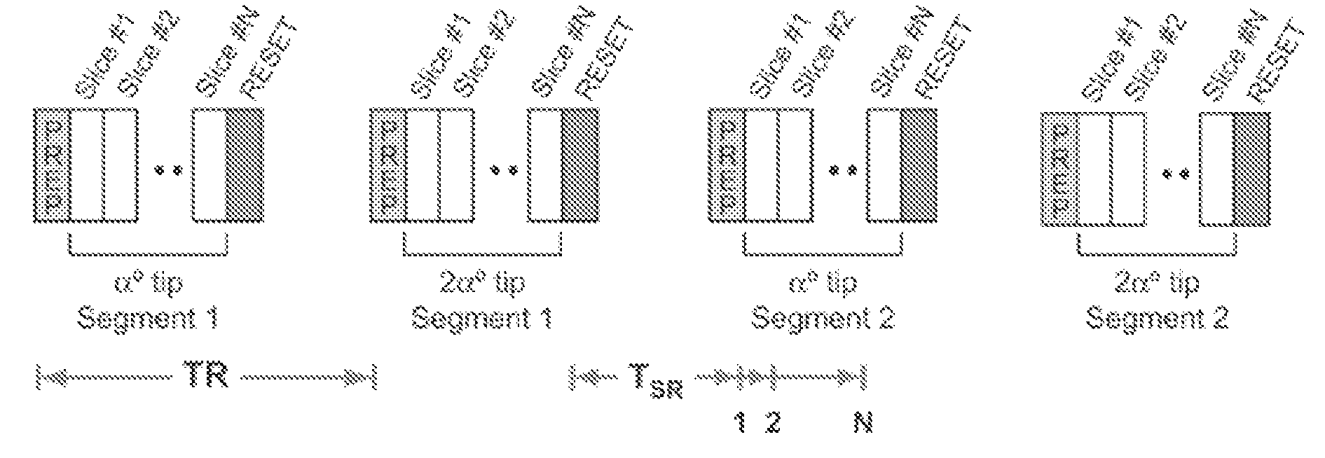
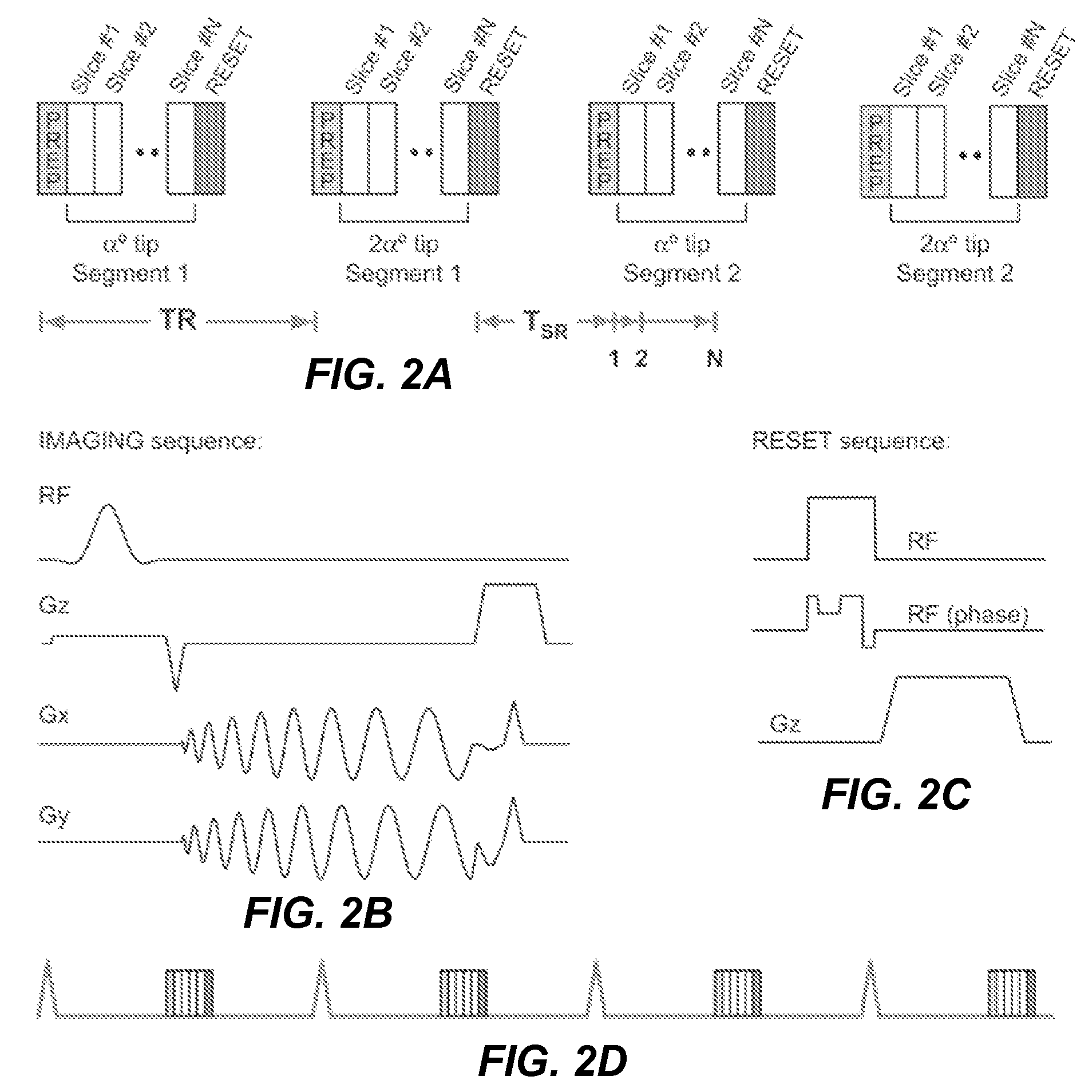
[0016]The proposed method uses an adaptation of the double angle method (DAM) described previously. Such methods allow calculation of a flip-angle map, which is an indirect measure of the B1+ field. Two images are acquired: I1 with prescribed tip angle α1 and I2 with prescribed tip angle α2=2α1. All other signal-affecting sequence parameters are kept constant. For each voxel, the ratio of magnitude images satisfies

[0017]I2⁡(r)I1⁡(r)=sin⁢⁢α2⁡(r)⁢f2⁡(T1,TR)sin⁢⁢α1⁡(r)⁢f1⁡(T1,TR),

where r represents spatial position and α1(r) and α2(r) are tip angles that vary with the spatially varying B1+ field. If the effects of T1 and T2 relaxation can be neglected, then the actual tip angles as a function of spatial position satisfy

[0018]α⁡(r)=arc⁢⁢cos(I2⁡(r)|2⁢I1⁡(r)).

[0019]A long repetition time (TR≧5 T1) is typically used with the double-angle methods so that there is no T1 dependence in either I1 or I2 (i.e., f1(T1,TR)=f2(T1,TR)=1.0). Instead, the proposed method includes a magnetization-reset ...


PUM


Abstract

For in vivo magnetic resonance imaging at high field (≧3 T) it is essential to consider the homogeneity of the active B1 field (B1+), particularly if surface coils are used for RF transmission. A new method is presented for highly rapid B1+ magnitude mapping. It combines the double angle method with a B1-insensitive magnetization-reset sequence such that the choice of repetition time (TR) is independent of T1 and with a multi-slice segmented (spiral) acquisition to achieve volumetric coverage with adequate spatial resolution in a few seconds.

Description

STATEMENT REGARDING FEDERALLY SPONSORED RESEARCH OR DEVELOPMENT[0001]The U.S. Government has rights in the disclosed invention pursuant to NIH Grant No. HL074332 to Stanford University and the University of Southern California, and NIH Grant No. EB002992 to Stanford University.BACKGROUND OF THE INVENTION[0002]This invention relates generally to magnetic resonance imaging (MRI), and more particularly the invention relates to mapping the magnitude of RF fields in a MRI pulse sequence.[0003]Magnetic resonance imaging (MRI) requires placing an object to be imaged in a static magnetic field (B0), exciting nuclear spins in the object with a RF magnetic field (B1), and then detecting signals emitted by the excited spins as they precess within the magnetic field (B0). Through the use of magnetic gradient and phase encoding of the excited magnetization, detected signals can be spatially localized in three dimensions.[0004]For in vivo MRI at high field (≧3 T) it is essential to consider the h...

Claims


Application Information

Patent Timeline
Patent Type & Authority Patents(United States)
IPC IPC(8): G01V3/00
CPCG01R33/246G01R33/583G01R33/446G01R33/4824G01R33/4835G01R33/5607G01R33/561
Inventor CUNNINGHAM, CHARLES H.NAYAK, KRISHNA S.PAULY, JOHN M.
Owner THE BOARD OF TRUSTEES OF THE LELAND STANFORD JUNIOR UNIV
Why Eureka
Try Eureka