Supporting mechanism for storage drives

a technology of supporting mechanism and storage drive, which is applied in the direction of instruments, electrical apparatus casings/cabinets/drawers, instruments, etc., can solve the problem that the frame is not easily detached by vibration, and achieve the effect of restricting space usage and simple structure of the aforesaid supporting mechanism

Inactive Publication Date: 2008-11-04
INVENTEC CORP
View PDF18 Cites 7 Cited by
  • Summary
  • Abstract
  • Description
  • Claims
  • Application Information

AI Technical Summary

Benefits of technology

[0006]In order to solve the problems of the prior art, a primary objective of the present invention is to provide a supporting mechanism for a hard disk drive which has a simple structure, good stability, and is easily attached and detached.
[0007]In order to achieve the above objectives, the present invention provides a supporting mechanism for a hard disk drive disposed on a case of an electronic device. The supporting mechanism includes a plurality of fixing components disposed on the case and a frame with a plurality of fixing slots corresponding to the fixing components. A supporting element is disposed on a center region of the case and a through hole is located on the center region of the frame. The supporting element can penetrate the through hole, and the frame is fixed on the supporting element by a screwing component. As a result, the frame is not easily detached by vibration. Two fixing pieces are disposed on two sides of the frame respectively. The fixing pieces may be a resilient component such that the frame is attached and detached easily. The resilient component may include a blocking sheet that prevents the frame from moving upwards and downwards.
[0008]When the frame is attached to the case, the fixing slots on the frame are aimed at the fixing components and the supporting element is aimed at the through hole. Then, the frame is disposed in the case such that the supporting element penetrates the through hole. While the fixing components are being positioned in the fixing slots, the fixing component pushes the fixing piece having the blocking sheet and then is fixed by the blocking sheet. Thus, the frame is fixed to the case. Afterwards, the screwing component, which may be a thumbscrew, is used to fasten the frame and the supporting element. In the case of a thumbscrew, the frame can be screwed and fastened by hand such that the frame is not easily detached due to vibration. As such, the fixing components and the screwing component can be operated by hand and the actions are more convenient.
[0010]The supporting mechanism for a hard disk drive of present invention includes a plurality of fixing components disposed on a frame and a case with a plurality of fixing slots corresponding to the fixing components, thereby allowing the frame to be fixed to the case. A supporting element disposed on a center region of the case and the frame is screwed with the supporting element by a screwing component. The structure of the aforesaid supporting mechanism is simple and is operated by hand easily. Being small, the fixing components and pieces of the supporting mechanism occupy only a small volume, and, when disposed on the frame and the case respectively, do not unduly restrict space usage.

Problems solved by technology

As a result, the frame is not easily detached by vibration.

Method used


Image

  • Supporting mechanism for storage drives
  • Supporting mechanism for storage drives
  • Supporting mechanism for storage drives

Examples


Embodiment Construction

[0019]The descriptions below of specific embodiments are to illustrate the present invention. Others skilled in the art can easily understand other advantages and features of the present invention from the contents disclosed in this specification. The present invention can be carried out or applied through different embodiments. The details of this specification can be modified based on different viewpoints and applications yet still fall within the scope of the present invention.

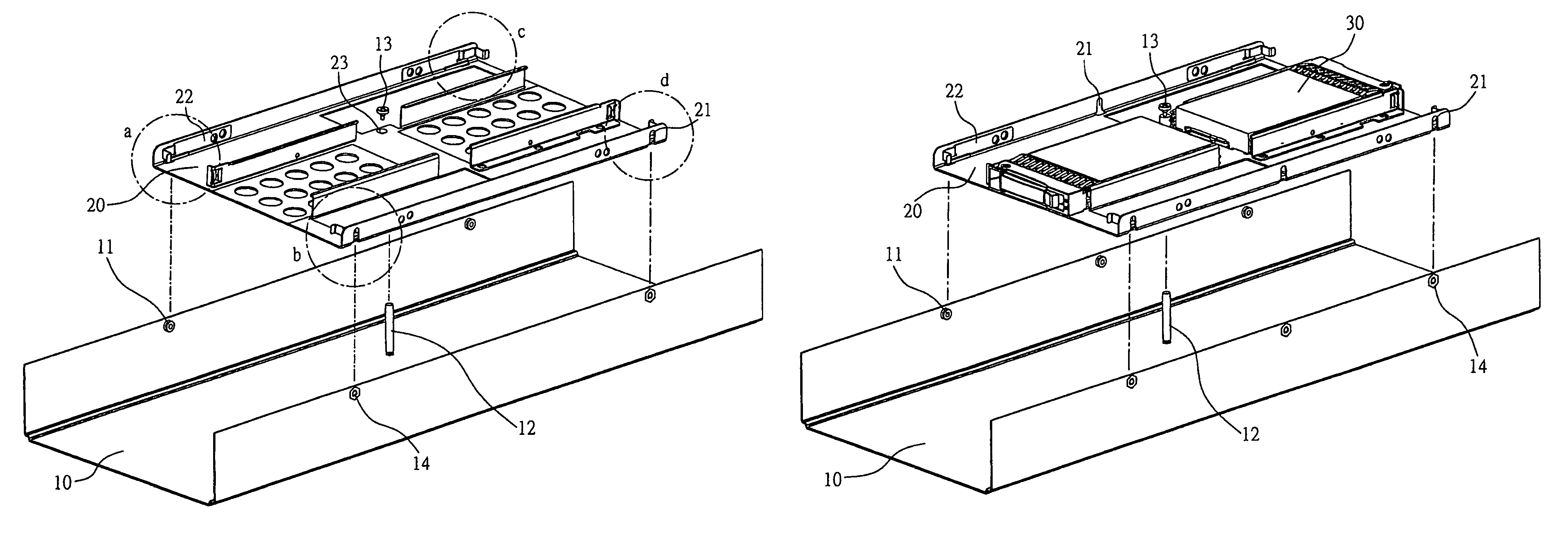
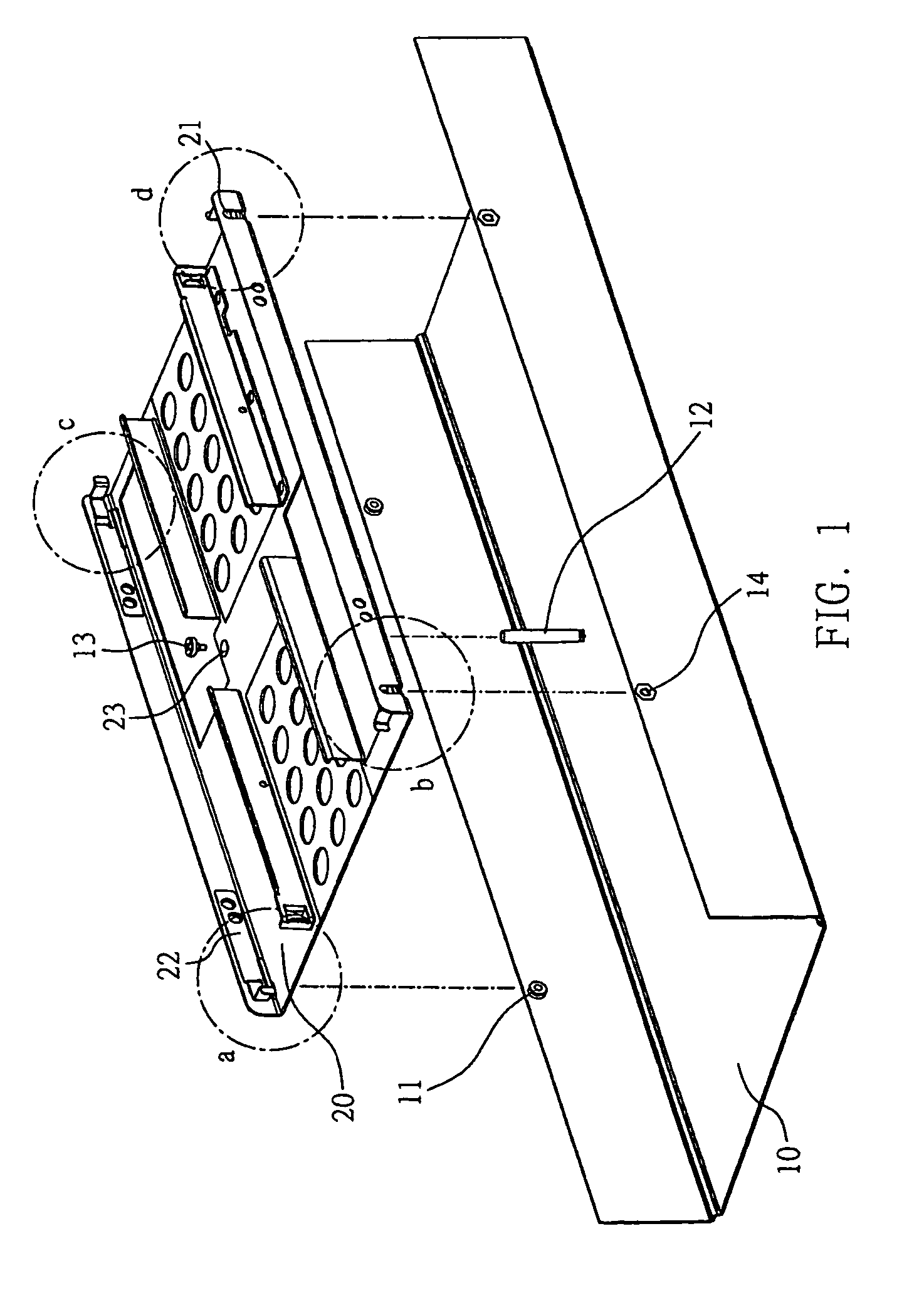
[0020]Referring to FIG. 1, a schematic diagram for a supporting mechanism for a hard disk drive of the present invention is shown. Four fixing components 11, which may be axial fixing components, are disposed on the case 10 of the electronic device. The case 10 may also be the motherboard of a computer if the storage drives are directly disposed on the motherboard.

[0021]The fixing components 11 are secured with fasteners such as nuts 14. Both sides of a frame 20 have fixing slots 21 corresponding to the fix...


PUM


Abstract

A supporting mechanism for storage drives is disclosed that includes a plurality of fixing components disposed on the sides of a case of an electronic device. Fixing slots corresponding to the fixing components are located on the case. A supporting element is disposed on the center region of the case and a through hole corresponding to the supporting element is located at the center region of the frame. The fixing components are fixed in the fixing slots, the supporting element penetrates the through hole, and the frame is fastened on the supporting element by a screwing component. Thus, the frame is not detached easily due to vibration or shaking. The fixing pieces are disposed on the sides of the frame and make the frame easily attachable and detachable.

Description

FIELD OF THE INVENTION[0001]The present invention relates to a supporting mechanism for storage drives, and more particularly, to a supporting mechanism for storage drives which is easily attached and detached from a case.DESCRIPTION OF THE PRIOR ART[0002]The storage demands for personal computers are continually increasing. In order to solve the problem that a storage drive does not have enough storage capacity, the use of more than one drive has become a common solution.[0003]In the conventional supporting mechanism for a storage drive, such as a hard drive, the storage drive is fixed to the PC case by riveting or screwing. Riveting is a method that involves the storage drive being riveted to the PC case and it can not be readily detached. Screwing is a method that involves the storage drive being fixed to the PC case by several screws such that it can be detached. However, the method of attaching and detaching a storage drive by screws involves having to screw or unscrew the scre...

Claims


Application Information

Patent Timeline
Patent Type & Authority Patents(United States)
IPC IPC(8): G06F1/16
CPCG06F1/187
Inventor CHEN, KUEI-HUA
Owner INVENTEC CORP
Why Eureka
Try Eureka