Optical apparatus and lens control method

a technology of optical apparatus and control method, which is applied in the direction of printers, instruments, cameras, etc., can solve the problems of image blur, inability to maintain the same focus state, and long time to return the focus lens, etc., and achieve the effect of suppressing image blur

Inactive Publication Date: 2008-11-04
CANON KK
View PDF5 Cites 6 Cited by
  • Summary
  • Abstract
  • Description
  • Claims
  • Application Information

AI Technical Summary

Benefits of technology

[0017]It is an object of the present invention to provide an optical apparatus and a lens control method for suppressing an image blur at the start of zooming.

Problems solved by technology

However, the in-focus state cannot be maintained by the same method when zooming from the wide-angle side to the telephoto side because one cam track that the focus lens should follow from the convergent point of the plurality of cam tracks cannot be determined.
Especially, in the telephoto side range in which the cam tracks disperse perfectly, if an error in determination of the cam track occurs once, it will take a long time to return the focus lens to the right cam track because of a long movement distance, and in the meantime, an image blur will occur.
However, in the conventional control method in which the large correction intensity is set in the middle zoom range, there are the following problems.
Although an image blur is not clearly visible in a taken-image when the object is fixed and the object distance is constant, a considerable image blur occurs when a camera work such as panning is performed or the object is moving.
Because when the AF evaluation value is changed according to the change of the taken-image due to the camera work or the movement of the object, misjudgment of an in-focus direction is caused, and the misjudgment in a high correction intensity condition causes a large movement of the focus lens in an out-of-focus direction.
However, strong correction of the focus lens to a side in which an image blur occurs according to the start of zooming causes a large image blur.
In this case, if the correction direction is reversed, it is not possible to find a right cam track because an increasing amount of the AF evaluation value is small.
Therefore, a situation in which zooming reaches the telephoto end with an image blur is caused.

Method used


Image

  • Optical apparatus and lens control method
  • Optical apparatus and lens control method
  • Optical apparatus and lens control method

Examples


embodiment

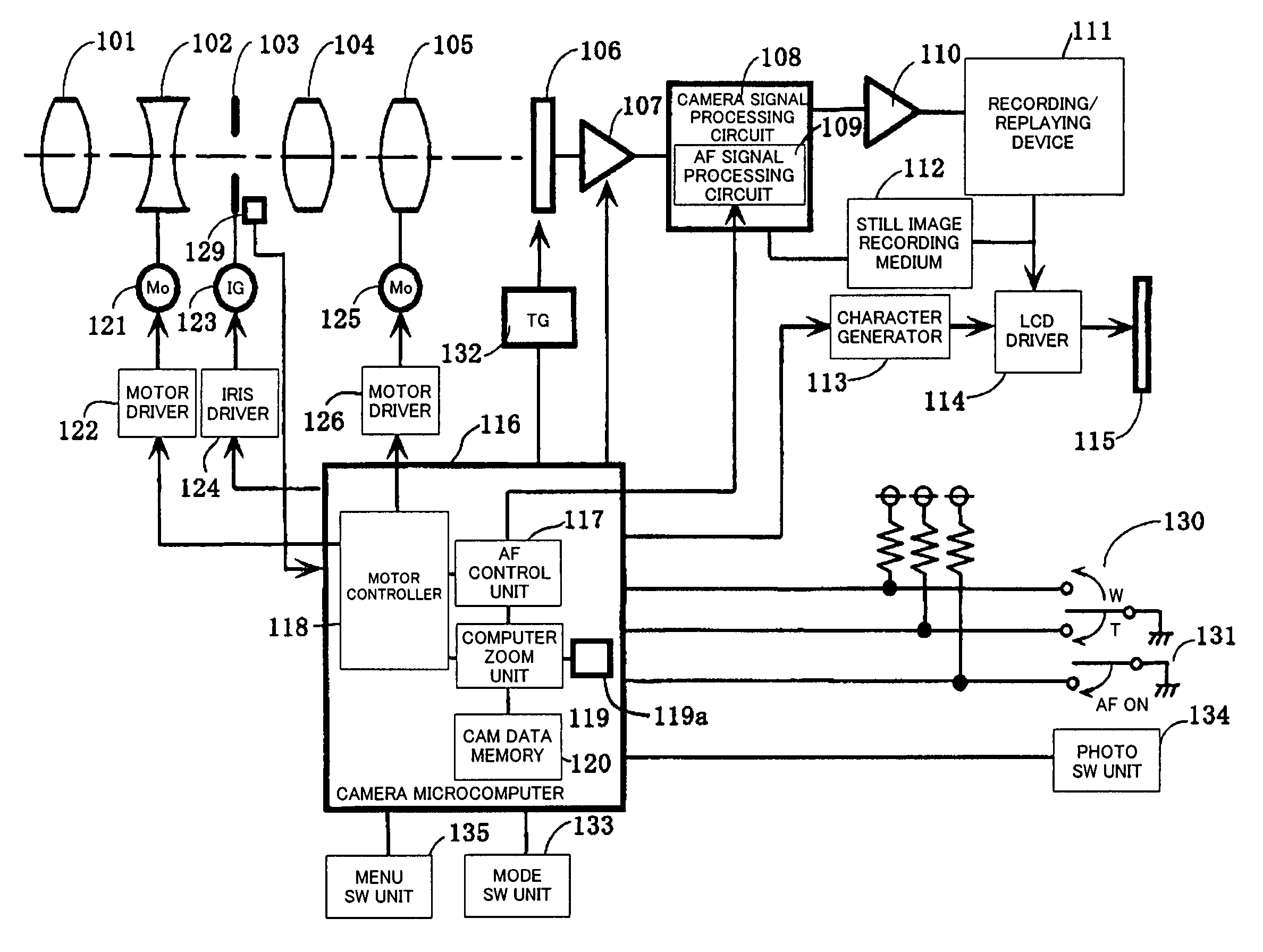
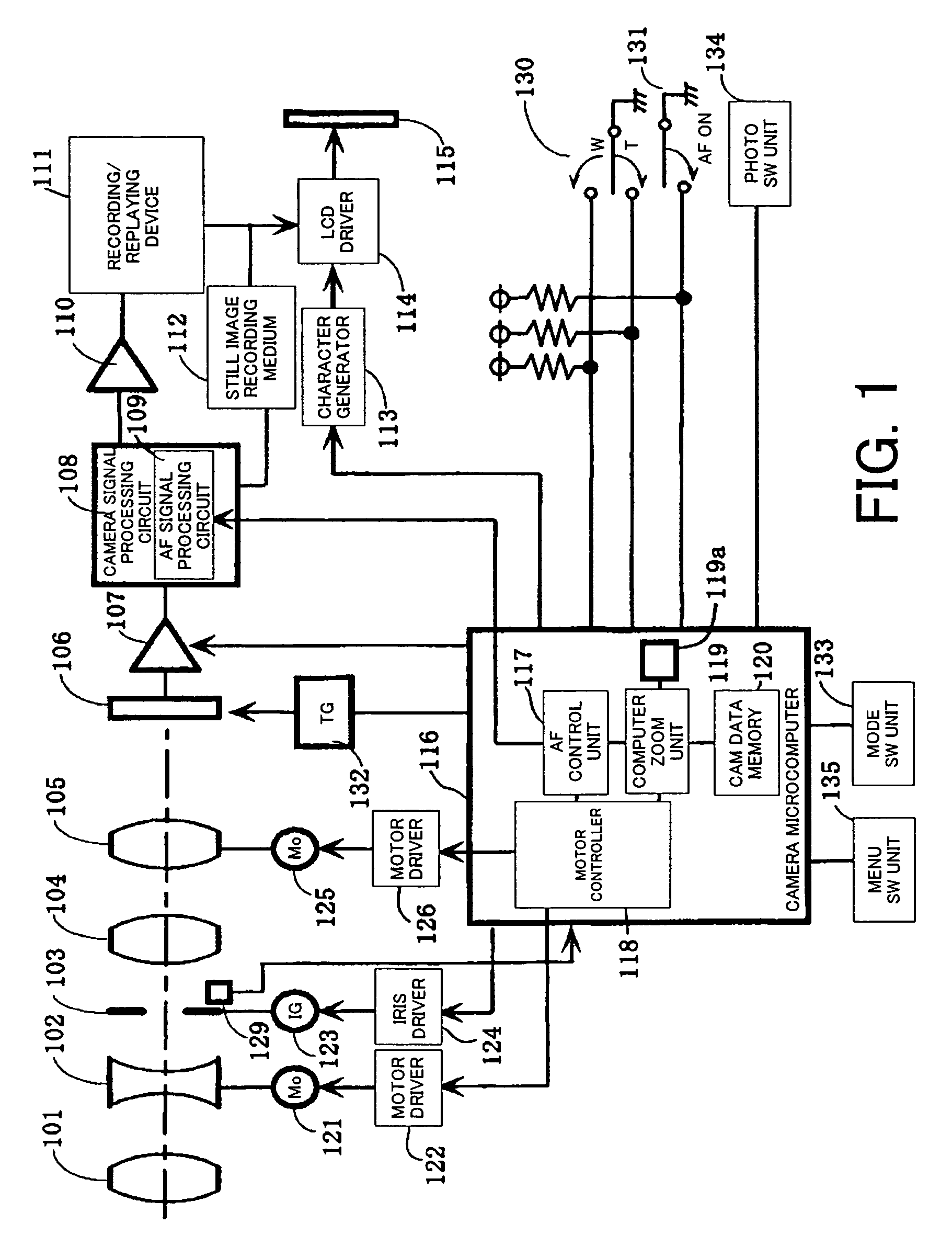
[0118]FIG. 1 shows the structure of a video camera as an image-taking apparatus (optical apparatus) that is an embodiment of the present invention. The present embodiment describes an image-taking apparatus having an image-taking lens integrally, to which the present invention is applied, however the present invention can also be applied to an interchangeable lens (optical apparatus) of an image-taking system constituted by the interchangeable lens and a camera main body on which the interchangeable lens is mounted. In this case, a microcomputer in the interchangeable lens performs the later-described zooming operation in response to a signal sent from the side of the camera main body (including an image-taking signal as a photoelectric conversion signal). Further, the present invention can be applied to not only such a video camera but also other image-taking apparatus such as a digital still camera.

[0119]In FIG. 1, in order from the object side (left side of the figure), reference...


PUM


Abstract

An optical apparatus is disclosed, which is capable of suppressing an image blur at the start of zooming. The optical apparatus comprises a memory storing data indicating the position of a second lens unit according to the position of a first lens unit, and a controller. The controller controls the drive width of the second lens unit at a third position with a first driving condition in a case where the drive of the first lens unit is started from a first position, and controls the drive width of the second lens unit at the third position with a second driving condition in a case where the drive of the first lens unit is started from a second position. The drive width of the second lens unit at the third position with the first driving condition is smaller than that with the second driving condition.

Description

FIELD OF THE INVENTION[0001]The present invention relates to lens control in optical apparatuses such as video cameras.BACKGROUND OF THE INVENTION[0002]Miniaturization of a camera body and image-taking (shooting) from as near position to an object as possible are requested in consumer use cameras with lenses. Therefore, an inner-focus lens is used mainly in the consumer use cameras, which corrects the movement of an image plane with the movement of a magnification lens by driving a correction lens according to cam track data without mechanically interlocking the correction lens and the magnification varying lens using a cam, and performs focusing by driving the correction lens. The cam track data instructs the movement track of the correction lens and are stored in a microcomputer.[0003]FIG. 7 shows the structure of a conventional inner focus lens system. In the Figure, 901 denotes a front lens, which is fixed, 902 denotes a zoom lens (magnification varying lens; it is also called a...

Claims


Application Information

Patent Timeline
Patent Type & Authority Patents(United States)
IPC IPC(8): G03B13/32G02B7/08G03B13/34
CPCG03B13/34
Inventor OKAWARA, HIROTO
Owner CANON KK
Why Eureka
Try Eureka