Optical fiber coupler and optical fiber therefor

a technology of optical fiber and coupler, applied in the field of optical fiber coupler, can solve the problems of inability to complete coupling and inability to achieve complete coupling, and achieve the effects of superior connectivity, low splicing loss, and superior optical characteristics

Inactive Publication Date: 2008-11-11
THE FUJIKURA CABLE WORKS LTD
View PDF15 Cites 0 Cited by
  • Summary
  • Abstract
  • Description
  • Claims
  • Application Information

AI Technical Summary

Benefits of technology

[0015]In order to solve the above-mentioned problems the present invention provides optical fiber for an optical fiber coupler and a fusion-elongated type optical fiber coupler that realize superior optical characteristics (coupling characteristics for lightwave having a wavelength in the vicinity of 1.55 μm) and superior connectivity with input / output optical fibers (low splicing loss).

Problems solved by technology

Accordingly, it is not possible that light power of a lightwave having a wavelength in the vicinity of 1.55 μm perfectly transfer from an 1.55 μm-band optical fiber to an 0.98 μm-band optical fiber; in other words complete coupling cannot be achieved.

Method used


Image

  • Optical fiber coupler and optical fiber therefor
  • Optical fiber coupler and optical fiber therefor
  • Optical fiber coupler and optical fiber therefor

Examples


first embodiment

[0076]It is sufficient to increase the refractive index of the optical fiber overall, especially the clad to increase the propagation constant β. However due to considerations of the environmental resistance properties and the mechanical reliability of optical fibers, it is preferable that the most external layer of the optical fiber be of pure SiO2 (quartz). If another element is added to adjust the relative refractive-index ratio this generally leads to deterioration in the environmental resistance properties and the mechanical reliability of the optical fiber. Thus, the second core 12b provides a region with a higher refractive index than the cladding 12c around the first core 12a of the 0.98 μm-band optical fiber.[0077](b) First Embodiment for Reduction of Propagation Constant Difference Δβ:

[0078]FIGS. 14 to 17 show elongation ratio dependence of the propagation constant difference Δβ of the 0.98 μm-band optical fiber shown in FIGS. 10 to 13 and the 1.55 μ-band single mode optic...

second embodiment

[0082]Further, it is evident that in the region where the elongation rate is 50% or smaller, in order to make the propagation constant difference Δβ equal to 10−4 rad / μm or smaller, the radius r(2) of the second core is preferably 10 μm or greater and the relative refractive-index difference Δ(2) of the second core 12b and the cladding 12c is preferably 0.1% or smaller. Moreover it is shown that when the relative refractive-index difference Δ(1) of the first core 12a of the 1.55 μm-band optical fiber 11 used for combination with the 0.98 μm-band optical fiber 12 is 0.35%, the relative refractive-index difference Δ(1) of the first core 12a of the 0.98 μm-band optical fiber 12 and the cladding 12c is preferably within the range from 0.7% to 0.9%.[0083](c) Second Embodiment for Reduction of Propagating Constant Difference Δβ:

[0084]FIGS. 18 to 21 show the results of elongation ratio dependence of the propagation constant difference Δβ of the 0.98 μm-band optical fiber shown in FIGS. 10 ...


PUM


Abstract

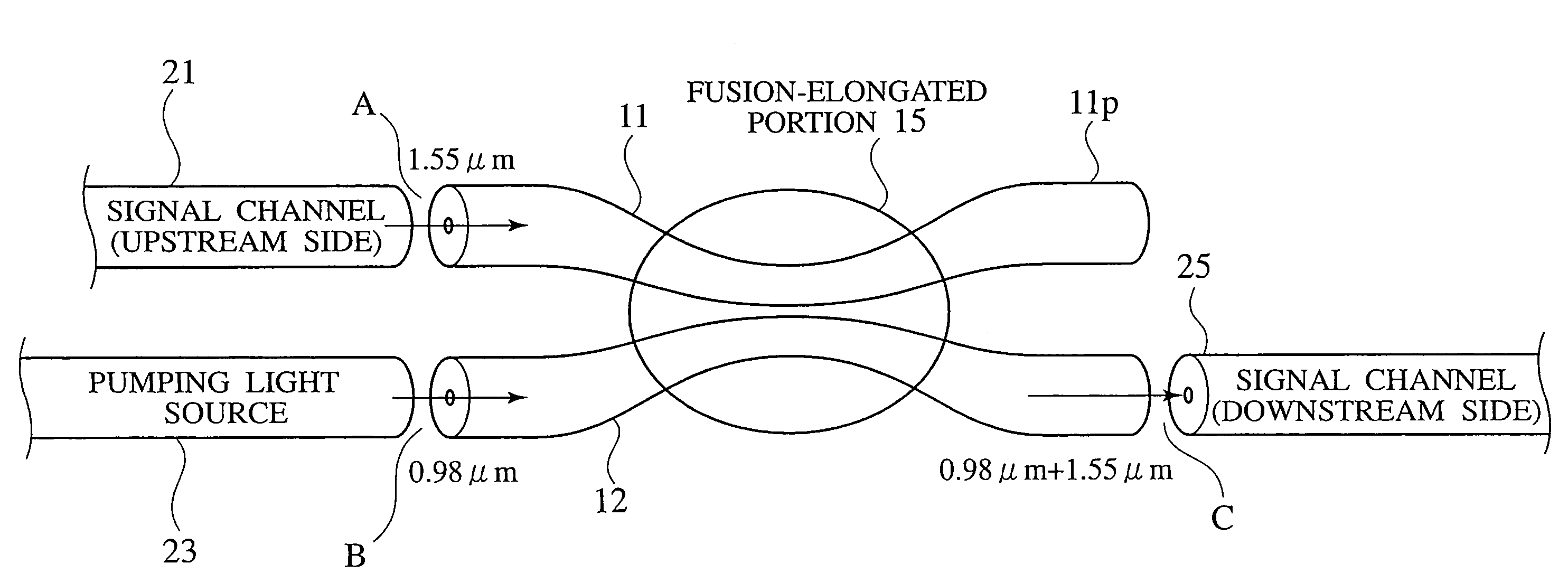
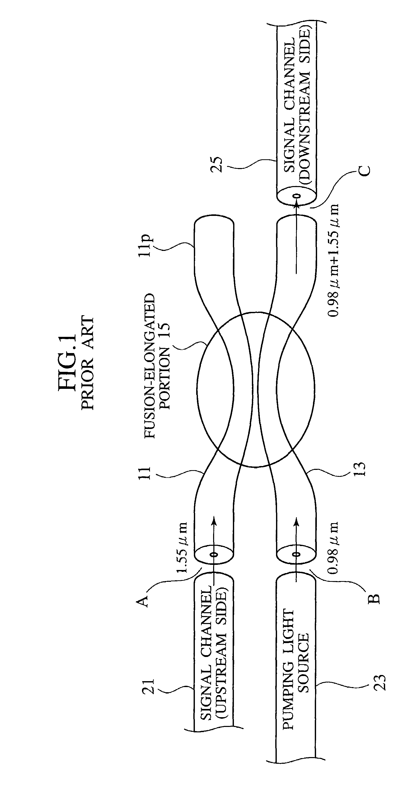
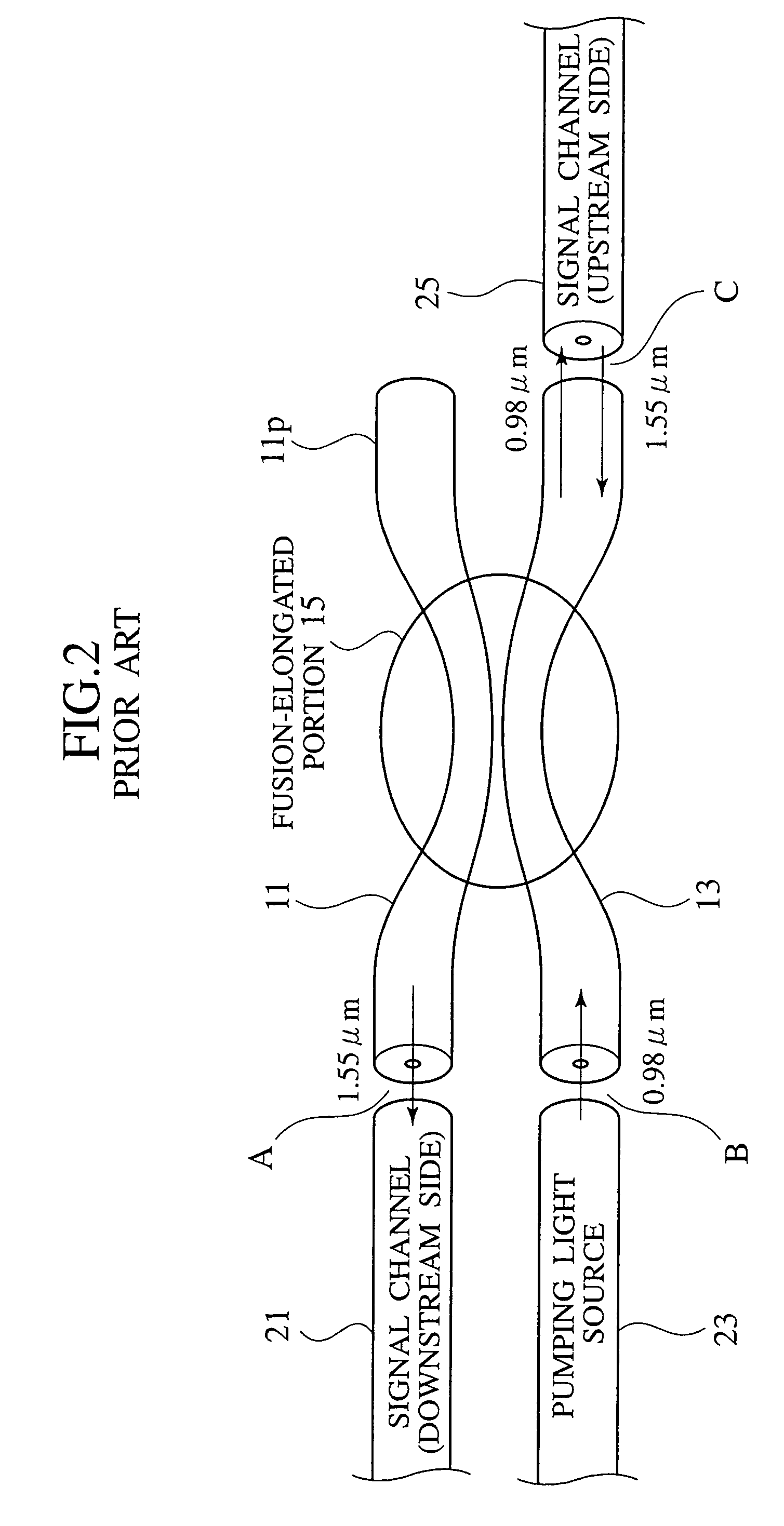
An optical fiber coupler is comprised of a fusion-elongated portion 15 in which an optical fiber 11 which is designed and fabricated for use at a wavelength in the vicinity of 1.55 μm and an optical fiber 12 which is designed and fabricated for use at a wavelength in the vicinity of 0.98 μm are fused and elongated. The propagation constant difference between optical fibers 11 and 12 is 10−4 rad / μm or smaller.

Description

[0001]Priority is claimed on Japanese application No. 2003-012664, filed Jan. 21, 2003, the content of which is incorporated herein by reference.BACKGROUND OF THE INVENTION[0002]The present invention relates to an optical fiber coupler used in the fields of optical information communication or optical measurement or the like, and more specifically, to a WDM (Wavelength-Division Mutiplexer) coupler that multiplexes / demultiplexes different wavelengths and an optical fiber for the optical fiber coupler.[0003]An EDFA (Erbium Doped Fiber Amplifier) is the main kind of amplifier recently used in the field of optical information communication. In an EDFA, pumping light having a wavelength in the vicinity of 1.48 μm or 0.98 μm is incident to excite a gain medium, i.e. an EDF (Erbium Doped Fiber) or a composite element thereof (Erbium). Here with a WDM coupler (hereinafter referred to as “optical fiber coupler”), a lightwave having a wavelength in the vicinity of 0.98 μm is incident to the g...

Claims


Application Information

Patent Timeline
Patent Type & Authority Patents(United States)
IPC IPC(8): G02B6/26G02B6/42G02B6/28G02B6/287
CPCG02B6/2835
Inventor ISHII, YUUMATSUMOTO, RYOKICHITANAKA, DAIICHIRO
Owner THE FUJIKURA CABLE WORKS LTD
Why Eureka
Try Eureka