Image forming apparatus, toner density control method, toner density control program and storage medium for storing the program

a toner density and program technology, applied in electrographic process apparatus, instruments, optics, etc., can solve the problems of insufficient toner density, inability to achieve high-quality images, and inability to perform toner supply without time delay, so as to prevent excessive toner supply and achieve the effect of preventing excessive toner supply

Inactive Publication Date: 2008-11-11
SHARP KK
View PDF16 Cites 10 Cited by
  • Summary
  • Abstract
  • Description
  • Claims
  • Application Information

AI Technical Summary

Benefits of technology

[0012]The present invention was made in view of the foregoing problems, and its object is to provide an image forming apparatus, a toner density control method, and a toner density control program, each of which can prevent excessive supply of toner and perform toner supply without time delay.
[0013]In order to solve the problems, an image forming apparatus according to the present invention is an image forming apparatus for developing, on a recording medium, an image corresponding to image data, by use of two-component developer constituted of toner and carrier, the image forming apparatus comprising: a developing chamber for containing the two-component developer used for development of the image; a supply member for supplying toner to the developing chamber; a toner consumption amount calculation section for calculating, based on the image data, an amount of toner consumption accompanying development of the image corresponding to the image data; a corrected consumption amount calculation section for calculating a corrected consumption amount by multiplying the calculated amount of toner consumption by a predetermined correction ratio that is less than 1; and a toner density control section for causing the supply member to perform main supply in which toner is supplied to the developing chamber based on the calculated corrected consumption amount and for controlling toner density of the two-component developer contained in the developing chamber.
[0015]With the image forming apparatus and the toner density control method, an amount of toner consumption accompanying development of an image corresponding to the image data is calculated based on image data, and toner is supplied to the developing chamber based on a corrected consumption amount calculated by multiplying the calculated amount of toner consumption by a predetermined correction ratio that is less than 1. In this way, by controlling toner supply based on the amount of toner consumption calculated from image data, it is possible to supply toner with little time delay from actual toner consumption. Further, by controlling an amount of toner supply based on the corrected consumption amount calculated by multiplying the calculated amount of toner consumption by a predetermined correction ratio that is less than 1, it is possible to prevent excessive supply of toner and suitably control an amount of toner supply even when there is a difference between the amount of toner consumption calculated from image data and the amount of actual toner consumption.
[0016]The toner density control program according to the present invention causes a computer to carry out the toner density control method. By causing a computer to read the program, it is possible for the computer to realize processing of each step in the toner density control method according to the present invention.
[0017]Further, by storing the program in a computer-readable storage medium, it is possible to easily maintain and distribute the program. Further, by causing a computer to read the storage medium, it is possible for the computer to carry out the processing of each step in the toner density control method according to the present invention.

Problems solved by technology

However, as in the techniques disclosed in Japanese Laid-Open Patent Publication No. 215575 / 1986, Japanese Laid-Open Patent Publication No. 207214 / 1998, and Japanese Laid-Open Patent Publication No. 151375 / 2004, when toner supply is controlled based on the result of detection carried out by the toner density sensor, it takes time to actually supply toner after detecting the toner density, and accordingly supply operation is delayed.
Therefore, toner density tends to be insufficient.
Therefore, quality of an image developed on a recording material inevitably drops.

Method used


Image

  • Image forming apparatus, toner density control method, toner density control program and storage medium for storing the program
  • Image forming apparatus, toner density control method, toner density control program and storage medium for storing the program
  • Image forming apparatus, toner density control method, toner density control program and storage medium for storing the program

Examples


Embodiment Construction

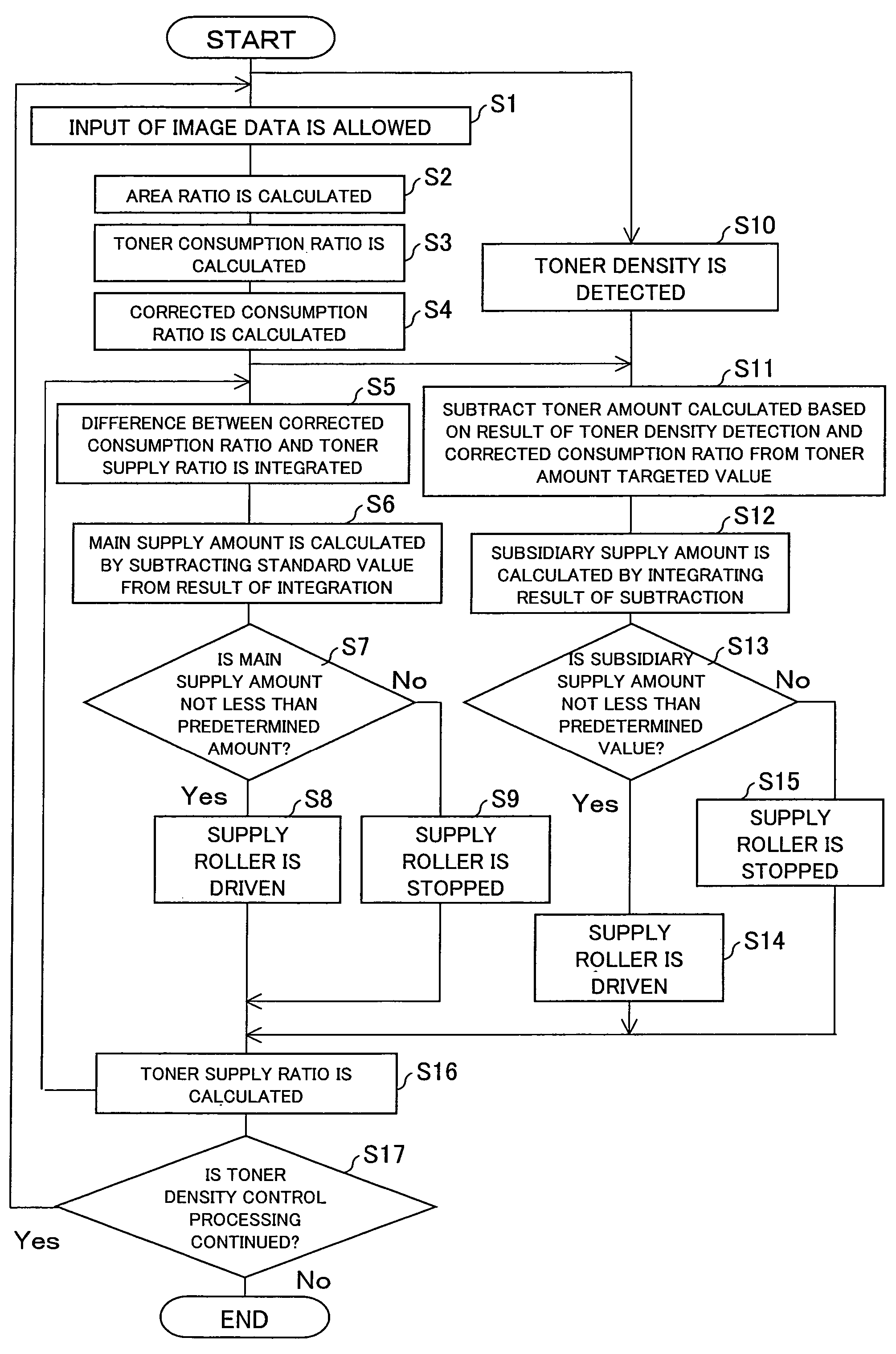
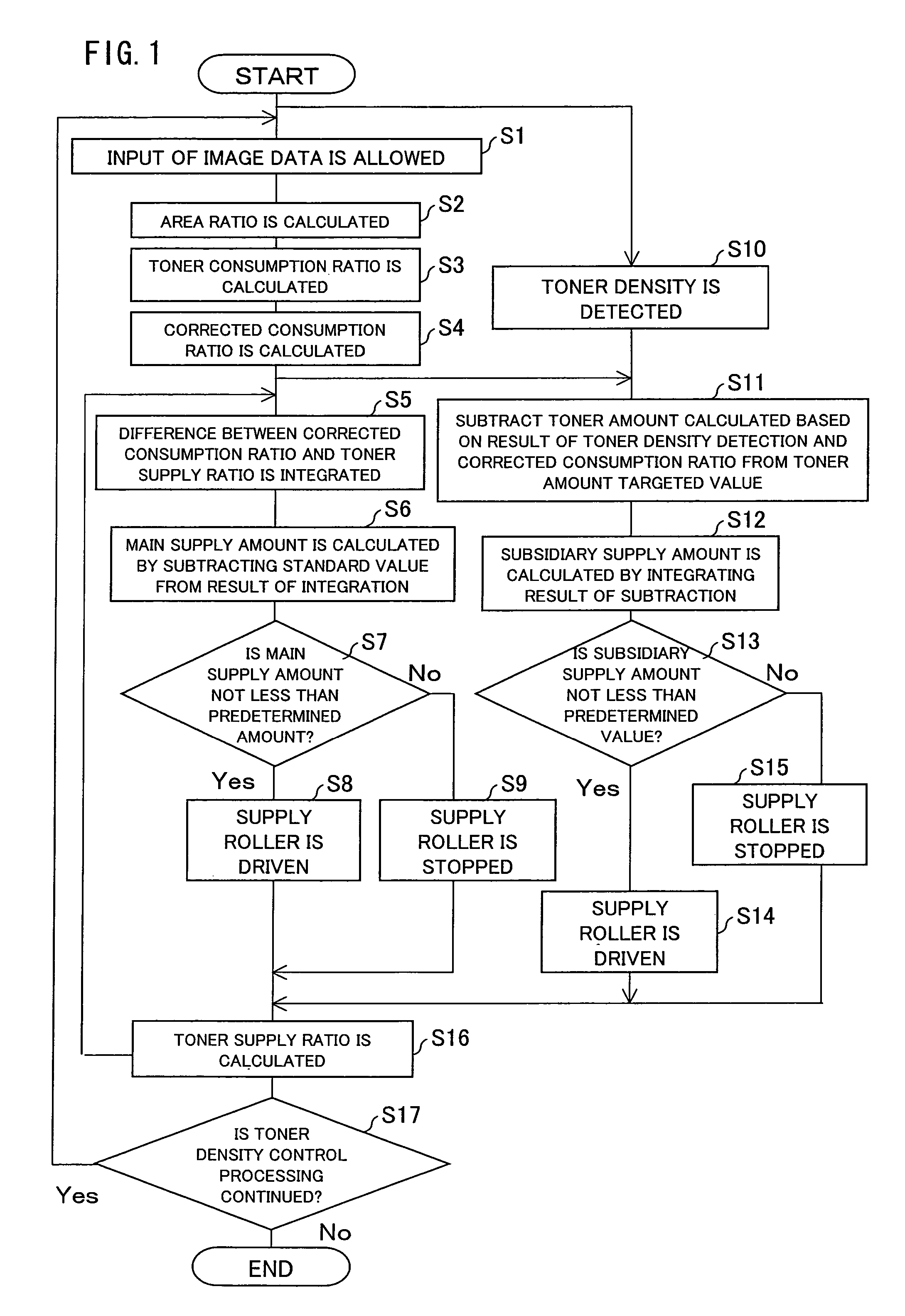
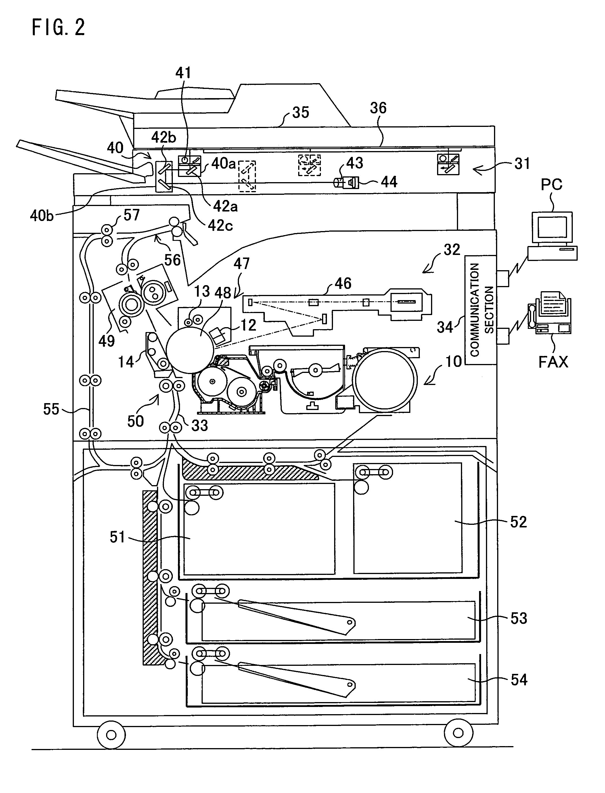
[0025]One embodiment of the present invention is explained below with reference to figures. FIG. 2 is a cross sectional view schematically illustrating a structure of a copying machine 30 corresponding to an image forming apparatus according to the present embodiment. The copying machine 30 includes a developing device 10 that uses developer (two-component developer) made by combining toner and carrier (magnetic carrier).

[Structure of Copying Machine 30]

[0026]The copying machine 30 functions as a copying machine, a printer, and a facsimile device, and includes a scanner section 31, a communication section 34, and a laser printer section 32.

[0027]The scanner section 31 includes: a document placement table 35 made of transparent glass; a double-sided automatic document feeder (RADF; (Recirculating Automatic Document Feeder) 36 for automatically feeding and conveying a document to the document placement table 35; and a scanner unit 40 (document image reading unit for scanning and readi...


PUM


Abstract

An amount of toner consumption accompanying development of an image corresponding to the image data is calculated based on image data, and a corrected consumption amount is calculated by multiplying the calculated amount of toner consumption by a predetermined correction ratio that is less than 1. Further, toner is supplied based on the calculated corrected consumption amount. As a result, it is possible to prevent excessive supply of toner, and to supply toner without time delay.

Description

[0001]This non-provisional application claims priority under 35 U.S.C. § 119(a) on Patent Application No. 2004-359007 filed in Japan on Dec. 10, 2004, the entire contents of which are hereby incorporated by reference.FIELD OF THE INVENTION[0002]The present invention relates to an image forming apparatus using two-component developer, a toner density control method, a toner density control program, and a storage medium for storing the program.BACKGROUND OF THE INVENTION[0003]Conventionally, each of electrophotographic image forming apparatuses (printing apparatuses) such as copying machines, printers and facsimiles is provided with a photoconductor drum, a charge device, an exposure device, a developing device, a transfer device, a fixing device, and the like.[0004]In the image forming apparatus, the exposure device performs exposure with respect to a photosurface (electrostatic latent image face) of the photoconductor drum charged by the charge device so as to form an electrostatic ...

Claims


Application Information

Patent Timeline
Patent Type & Authority Patents(United States)
IPC IPC(8): G03G15/08
CPCG03G15/0853G03G15/0849
Inventor ITOYAMA, MOTOYUKIISHII, HIROSHI
Owner SHARP KK
Why Eureka
Try Eureka