Fuel cell system, and electronic device

A fuel cell system and fuel technology, used in fuel cells, fuel cell additives, fuel cell components, etc., can solve problems such as instability and output reduction, and achieve high power consumption, high output, and improved stability. Effect

Inactive Publication Date: 2010-08-11
SONY CORP
View PDF0 Cites 1 Cited by
  • Summary
  • Abstract
  • Description
  • Claims
  • Application Information

AI Technical Summary

Problems solved by technology

Therefore, causing the output to decrease or become unstable

Method used


Image

  • Fuel cell system, and electronic device
  • Fuel cell system, and electronic device
  • Fuel cell system, and electronic device

Examples


no. 1 approach

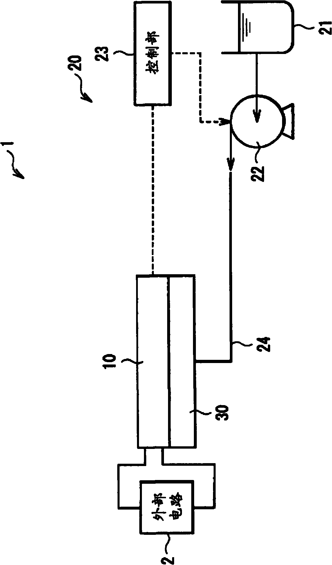
[0053] figure 1 A schematic structure of an electronic device having the fuel cell system according to the first embodiment of the present invention is shown. The electronic device is, for example, an electronic device such as a mobile phone and a notebook PC (Personal Computer). The electronic device includes a fuel cell system 1 and an external circuit (load) 2 driven by electric energy generated by the fuel cell system 1 . For example, the fuel cell system 1 includes a power generation unit 10 , a fuel supply control unit 20 , and a fuel vaporization unit 30 .

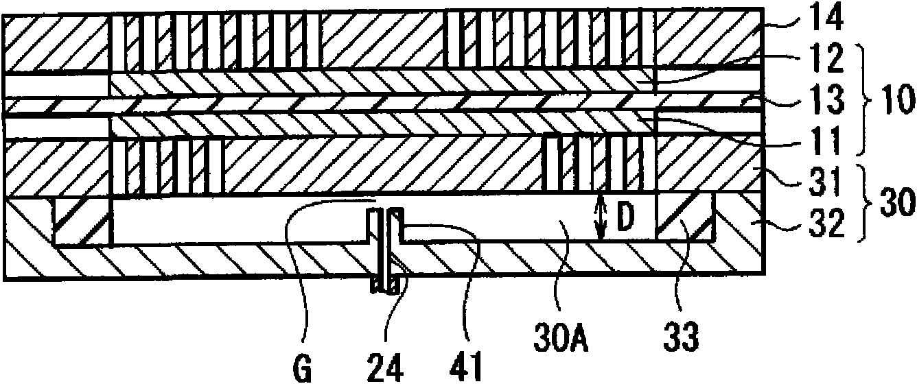
[0054] figure 2 One example of the power generation section 10 and the fuel vaporization section 30 is shown. For example, the power generation unit 10 is a DMFC including an electrolyte membrane 13 interposed between an anode 11 and a cathode 12 . The anode 11 and the cathode 12 have a structure in which a catalyst layer containing platinum (Pt), ruthenium (Ru) or the like is formed on the surface of carbon cl...

no. 2 approach

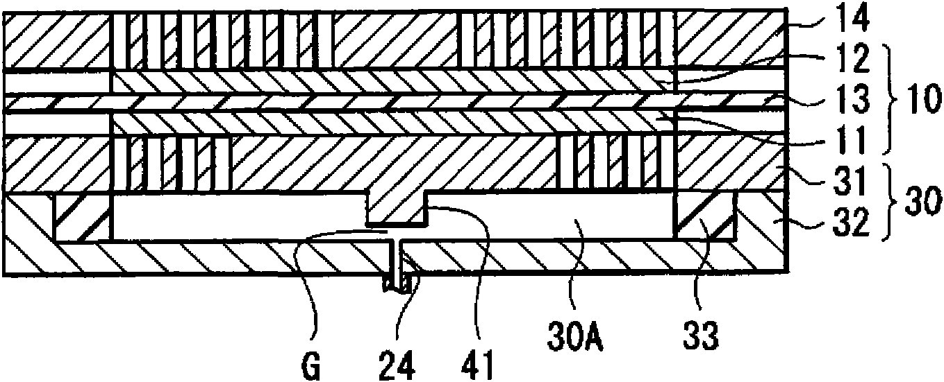
[0079] Figure 4 and Figure 5 The structures of the power generation section 10 and the fuel gasification section 30 according to the second embodiment of the present invention are shown. This embodiment has the same structure as the above-mentioned first embodiment except that the end of the protrusion 41 is in contact with Figure 4 The inner wall surface of the outer member 32 is in contact with the protrusion 41 and the Figure 5 The inner wall surface of the inner member 31 is in contact, and this embodiment can be manufactured in the same manner as the first embodiment described above.

[0080] The protrusion 41 is in contact with the inner wall surface of the outer member 32 or a portion on the inner wall surface of the inner member 31 adjacent to the end of the fuel supply passage 24 . Therefore, in this embodiment, the heat of the power generation part 10 is conducted to the outer member 32 or the inner member 31 through the protrusion 41 . Heat is conducted to t...

no. 3 approach

[0082] Figure 6 The structures of the power generation section 10 and the fuel gasification section 30 according to the third embodiment of the present invention are shown. In this embodiment, a diffuser plate 50 that diffuses the liquid fuel supplied to the vaporization chamber 30A is provided on the inner wall surface of the outer member 32 . Therefore, in this embodiment, the liquid fuel supplied from the fuel supply passage 24 is diffused in the planar direction by the diffusion layer 50, and the fuel can be vaporized more efficiently and uniformly.

[0083] The diffuser plate 50 is made of resin such as porous polyethylene and porous polypropylene. The diffuser plate 50 is provided at or near the outlet of the fuel supply passage 24 . Ends of the protrusions 41 may be in contact with the diffuser plate 50 . In addition, a gap G may be provided between the end of the protrusion 41 and the diffuser plate 50 .


PUM


Abstract

Provided are a fuel cell system which can avoid an excess or insufficient feed of a gasified fuel thereby to generate an electric power stably in a high output, and an electronic device using the system. In a carburetor chamber (30A), a protrusion (41) is formed as a heat transfer portion for transferring the heat generated in a generator unit (10), to a liquid fuel fed to the carburetor chamber (30A). Between the leading end of the protrusion (41) and the inner wall face of an inner member (31), there is formed a gap (G), in which the liquid fuel fed from the leading end of a fuel feed passage (24) is gasified by transferring the heat efficiently to it. The protrusion (41) may also contact the inner wall face of the inner member (31) near the leading end portion of the fuel feed passage (24), thereby to transfer the heat of the generator unit (10) to the inner member (31) through the protrusion (41) so that the liquid fuel may be gasified by transferring the heat to it through the inner member (31). Thus, the area to be heated can be restricted according to the position of the protrusion (41), and the quantity of the heat to be transferred to the liquid fuel can also be controlled according to the size of the protrusion (41).

Description

technical field [0001] The present invention relates to a fuel cell system and an electronic device using the fuel cell system. Background technique [0002] A fuel cell has a structure in which an electrolyte is provided between an anode electrode (fuel electrode) and a cathode electrode (oxygen electrode). Fuel is supplied to the anode electrode and oxidant is supplied to the cathode electrode. At this time, a redox reaction in which the fuel is oxidized by the oxidizing agent starts, and chemical energy contained in the fuel is converted into electrical energy. [0003] Such a fuel cell is capable of continuously generating electricity by continuously supplying fuel and oxidant. Thus, fuel cells are considered to be new energy sources for mobile electronic devices different from existing primary batteries or existing secondary batteries. That is, since the fuel cell generates electricity by utilizing the reaction between the fuel and the oxidant, if oxygen in the air i...

Claims


Application Information

Patent Timeline
Patent Type & Authority Applications(China)
IPC IPC(8): H01M8/04H01M8/02H01M8/10
CPCH01M8/04089Y02E60/50H01M8/04074
Inventor 高木裕登福岛和明志村重辅
Owner SONY CORP
Why Eureka
Try Eureka