Crushing apparatus

A crushing device and crushing technology, which is applied in transportation and packaging, solid separation, filtering, etc., can solve problems such as longer recovery time and oil pressure loss, reduce fuel consumption, reduce oil pressure loss, and increase operations volume effect

Inactive Publication Date: 2006-11-29
KOMATSU LTD
View PDF0 Cites 2 Cited by
  • Summary
  • Abstract
  • Description
  • Claims
  • Application Information

AI Technical Summary

Problems solved by technology

[0011] As a result, the time to reach recovery will be longer
Also, oil pressure loss due to decompression of the oil pressure circuit will occur

Method used


Image

  • Crushing apparatus
  • Crushing apparatus
  • Crushing apparatus

Examples


Embodiment approach 1

[0084] [1] Overall composition

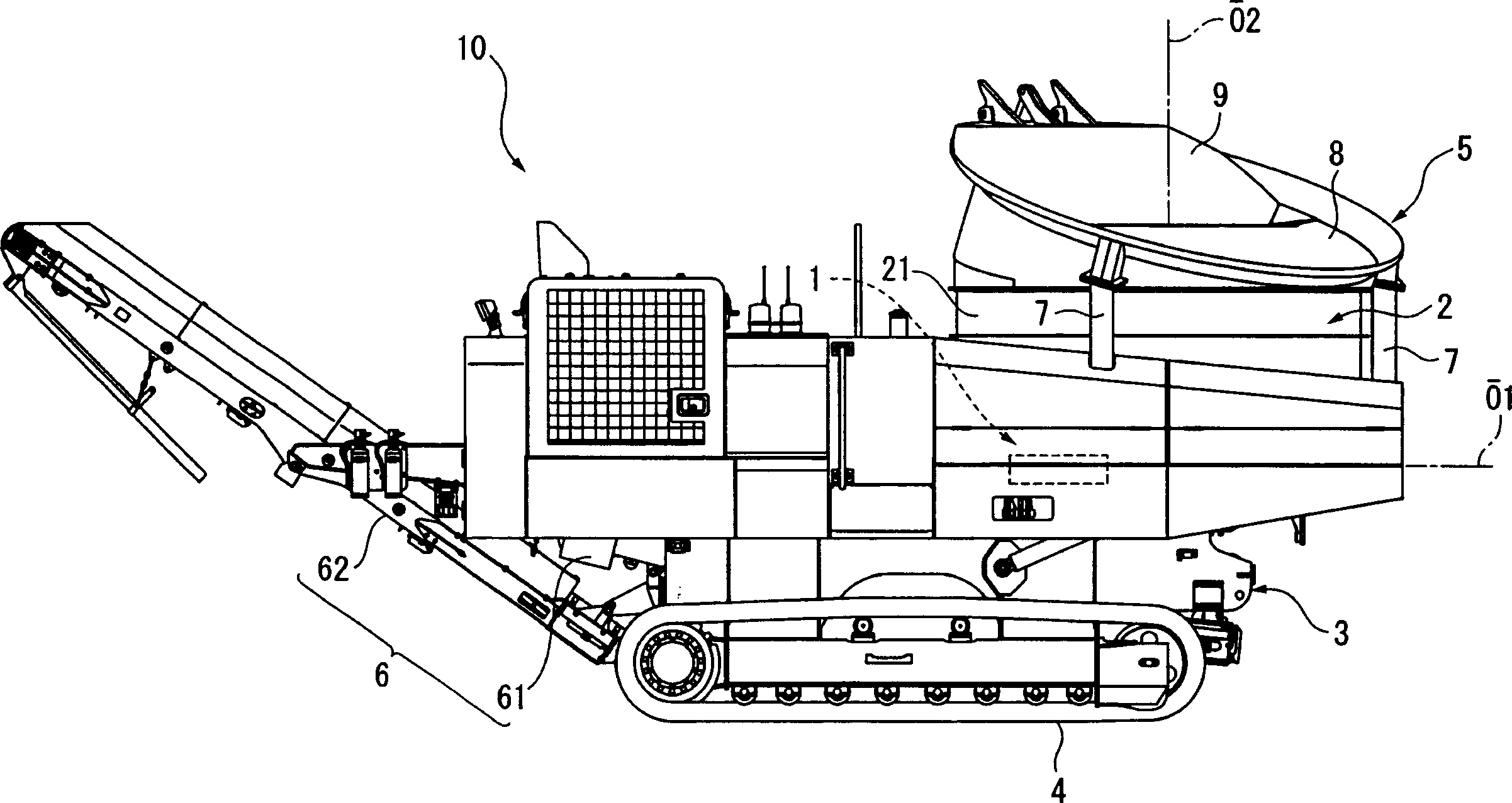
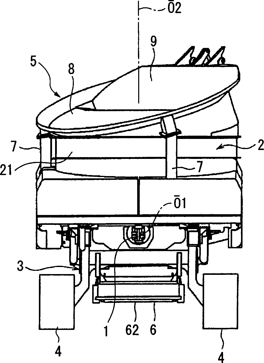
[0085] Next, specific embodiments of the crushing device of the present invention will be described in detail with reference to the accompanying drawings. figure 1 is a side view of the wood breaking plant, figure 2 is its rear view.

[0086] This wood shredder is self-propelled, and includes a shredder 1 and a substantially cylindrical drum (rotary drum) 2 that rotates around an axis O2 to supply wood to the shredder 1 .

[0087] In addition, a drum receiving frame for attaching the drum 2 around the axis, a crusher 1, etc. are attached to a chassis (machine body) 3, and a running body 4 is attached to the chassis 3. In addition, a hopper (fixed hopper) 5 is attached to the upper opening of the drum 2 , and wood is supplied into the drum 2 by putting wood into the hopper 5 .

[0088] Crusher 1 as figure 1 and figure 2 As shown, it includes a rotating shaft rotating around an axis O1 extending in the traveling direction of the wood cru...

Embodiment approach 2

[0236] Next, Embodiment 2 of the present invention will be described. In addition, in the following description, the description of the same parts as those already described will be omitted or simplified.

[0237] In the crushing device according to Embodiment 1 described above, the first hydraulic motor 1A is a variable displacement motor capable of changing displacement only by its own pressure.

[0238] In contrast, in the crushing device of Embodiment 2, such as Figure 13 As shown, a solenoid 202 is connected to the first hydraulic motor 201A, and the solenoid 202 is set for setting the change in capacity of the first hydraulic motor 201A.

[0239] When the operator sets the capacity setting switch of the first hydraulic motor 201A on the operation panel to ON, the first hydraulic motor 201A is set to the small capacity side by the solenoid 202, and when the capacity setting switch is set to When off, it is set to the large capacity side. Moreover, the switching of the...

Embodiment approach 3

[0246] Next, Embodiment 3 of the present invention will be described.

[0247] In the above-described second embodiment, the solenoid 202 provided on the first hydraulic motor 201A is provided for the operator to set the capacity of the first hydraulic motor 201A.

[0248] In contrast, in the crushing device of Embodiment 3, such as Figure 15 As shown, the first hydraulic motor 301A is not a motor of the type whose capacity is switched by its own pressure, but a motor of the type whose capacity is switched by exciting the attached solenoid 302 . different.

[0249] As the trigger sensor for switching the capacity of the first hydraulic motor 301A by the solenoid 302, in this embodiment, the pressure sensor 303 is used in the pump line 161A, and the output of the pressure sensor 303 is controlled by the controller 30. process to energize the solenoid 302 .

[0250] The control structure inside the controller 30 is like Figure 16 As shown in the functional block diagram, t...


PUM


Abstract

A rotary crushing apparatus having a hydraulic motor for driving a crusher, comprising a load detection means detecting the loading state of the hydraulic motor, a load determination means determining the loading state of the hydraulic motor, a supply amount control means which, when the hydraulic motor is determined to be overloaded by the load determination means, stops the supply of crushed materials by a supply device and, when determined to be less loaded, starts to supply the crushed materials by the supply device, and a motor capacity control means which, when the motor is determined to be overloaded by the load determination means, changes the capacity of the variable displacement motor to a large capacity side. Since the capacity of the hydraulic motor is switched to the large capacity side when the supply device is stopped, the motor can crush wood in the crusher with a high torque and can be returned, under a low load, to the original state in a short time.

Description

technical field [0001] The invention relates to a crushing device for crushing wood, rocks and other crushed objects. Background technique [0002] As a crushing device, there is a self-propelled crushing machine (for example, refer to Patent Document 1). [0003] The crushing machinery such as Figure 18 As shown, a rotary crusher (crushed body) 151 and a drum (rotary drum 152 ) that rotates separately from the axis and supplies wood (object to be crushed) to the rotary crusher 151 are provided. Furthermore, the drum 152, the crusher 151, and the like are attached to a body 153, and a traveling body 154 is attached to the body 153. In this way, wood (crushed material) is put into the drum 152 and crushed by the crusher 151 , and the crushed material is supplied below the crusher 151 and discharged to the outside by the conveying conveyor 155 . [0004] However, wood as objects to be crushed includes branches, trunks, roots, etc., and has various hardness and size, and is ...

Claims


Application Information

Patent Timeline
Patent Type & Authority Applications(China)
IPC IPC(8): B02C25/00B02C18/22B02C18/24
CPCB02C2018/164B02C18/24B02C25/00B02C18/2225B02C21/02B07B1/00B27L11/06B65G19/00
Inventor 梅田博之中岛刚介吉田哲幸
Owner KOMATSU LTD
Why Eureka
Try Eureka