MEMS sensor driving device, MEMS sensor driving method, and active sensor using MEMS

a technology of mems sensor and driving device, which is applied in the direction of turn-sensitive devices, television systems, instruments, etc., can solve the problems of resonant frequency and amplitude change, amplitude greatly changes, and difficulty in following a change in resonant frequency for a variation of samples or a change in temperature, etc., to achieve stable driving

Inactive Publication Date: 2008-11-18
SONY CORP
View PDF9 Cites 32 Cited by
  • Summary
  • Abstract
  • Description
  • Claims
  • Application Information

AI Technical Summary

Benefits of technology

[0007]In addition, a MEMS frequently has oscillation in a nonlinear region by using driving at a frequency in the vicinity of a spring elastic limit, a spring arcuate motion, or the like. However, when the MEMS is used at a frequency in the vicinity of a peak in frequency, a jump phenomenon occurs due to an effect such as disturbance, whereby the resonant frequency and amplitude of the MEMS change. Accordingly, it is difficult to obtain expected gain or the like. To restore a normal state of the MEMS, it is necessary to set detailed conditions such as a free-run frequency, a frequency-scanning direction, and a scanning speed. This complicates a driving circuit for the MEMS.
[0014]According to an embodiment of the present invention, it is desirable to provide a MEMS sensor driving device and method, and a MEMS active sensor that perform stable driving in which a gain hardly changes even for a shift in resonant frequency for a change such as an externally environmental change such as a change in temperature.
[0019]According to an embodiment of the present invention, stable driving is realized in which a gain hardly changes even for a shift in resonant frequency for a change such as an externally environmental change such as a change in temperature.

Problems solved by technology

However, in the configuration in which the resonance frequency is externally input, it is difficult to follow a change in resonant frequency for a variation of samples or a change in temperature.
Thus, a problem occurs in that amplitude greatly changes due to an external environment or a variation of samples.
However, when the MEMS is used at a frequency in the vicinity of a peak in frequency, a jump phenomenon occurs due to an effect such as disturbance, whereby the resonant frequency and amplitude of the MEMS change.
Accordingly, it is difficult to obtain expected gain or the like.
This complicates a driving circuit for the MEMS.

Method used


Image

  • MEMS sensor driving device, MEMS sensor driving method, and active sensor using MEMS
  • MEMS sensor driving device, MEMS sensor driving method, and active sensor using MEMS
  • MEMS sensor driving device, MEMS sensor driving method, and active sensor using MEMS

Examples


first embodiment

[0052]FIG. 3 is a block diagram showing the configuration of a MEMS sensor driving device (hereinafter referred to as a “MEMS driving device”) according to the first embodiment of the present invention.

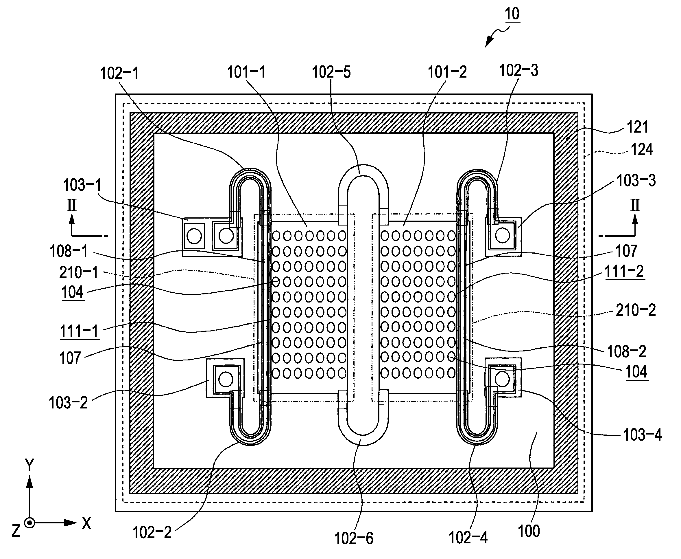
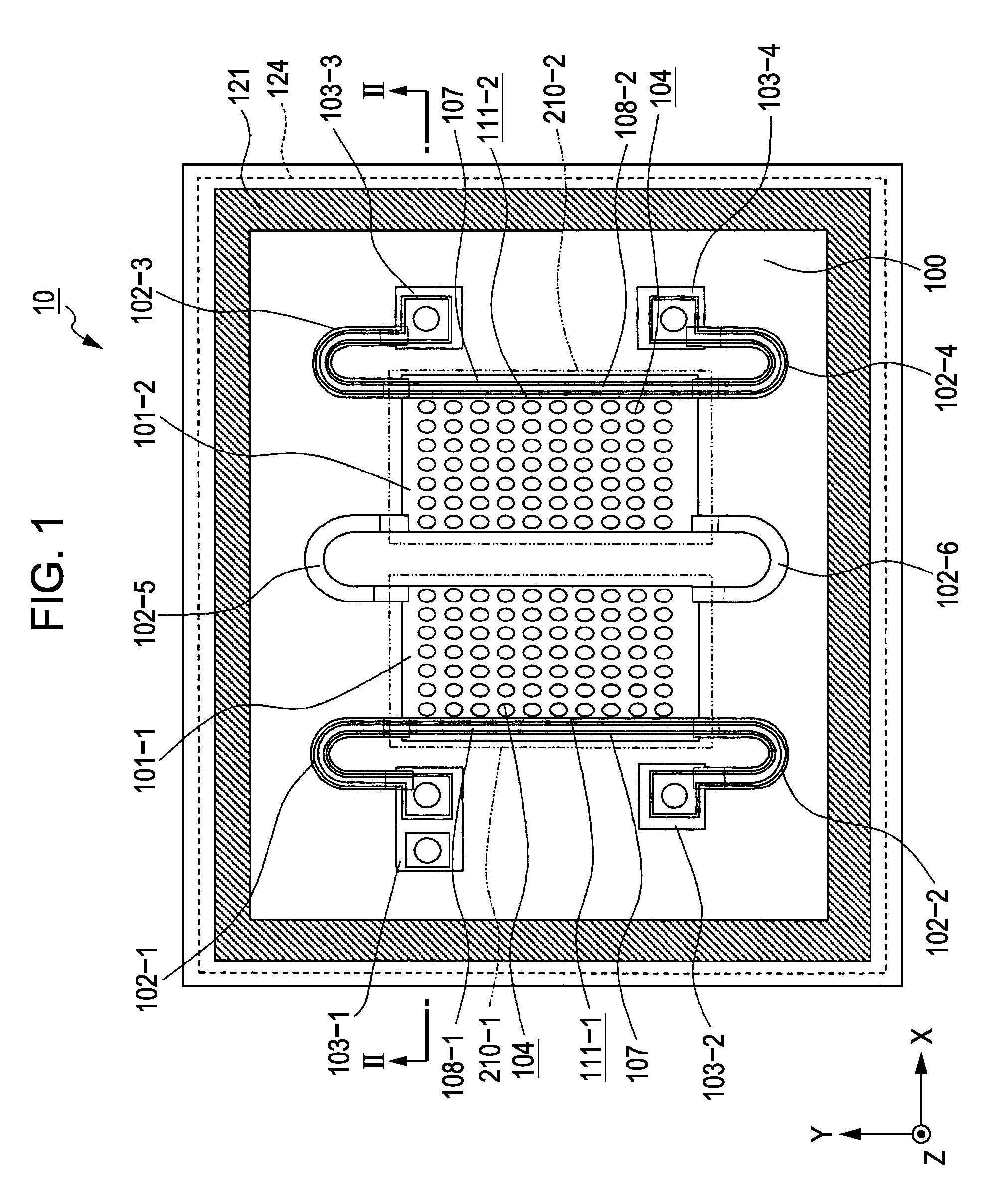
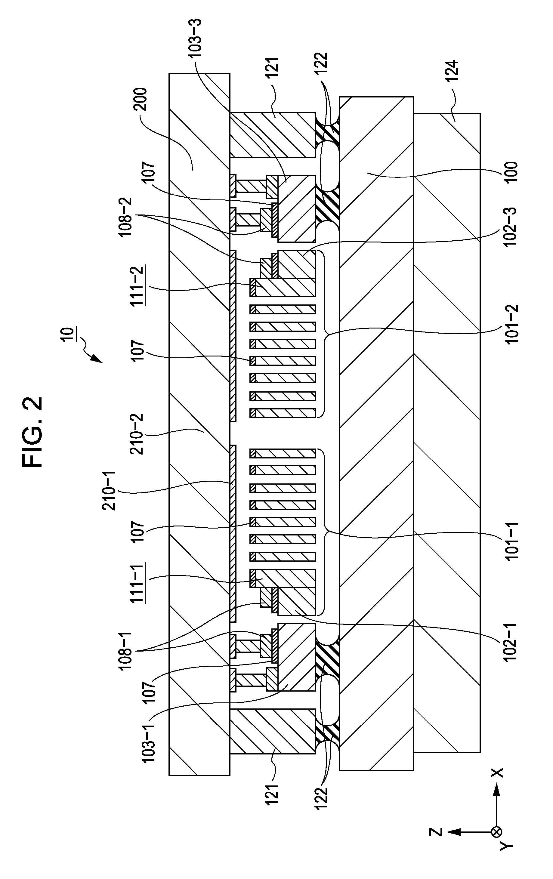
[0053]As shown in FIG. 3, the MEMS driving device according to the first embodiment includes a detecting unit 20 for detecting (monitoring) oscillation of oscillators (corresponding to the first and second oscillators 101-1 and 101-2 in FIGS. 1 and 2) of the MEMS sensor 10, and a feedback circuit 30 for amplifying a signal detected by the detecting unit 20 and inputting the amplified signal as a driving signal to the MEMS sensor 10.

[0054]As described above, the detecting unit 20 electromagnetically detects (monitors) the oscillation of the oscillators of the MEMS sensor 10. However, the detection principle of the detecting unit 20 is not limited to electromagnetic detection, but electrostatic detection, piezoelectric detection, or the like, may be used. In other words, any detection p...

second embodiment

[0079]FIG. 8 is a block diagram showing the configuration of a MEMS driving device according to a second embodiment of the present invention. In FIG. 8, portions identical to those shown in FIG. 8 are denoted by identical reference numerals.

[0080]As shown in FIG. 8, the MEMS driving device has a configuration having a driving system using a PLL circuit 40 in addition to the driving system using the feedback circuit 30 in the MEMS driving device according to the first embodiment. In this configuration, when the MEMS sensor 10 is activated, the feedback circuit 30 is used to allow the MEMS sensor 10 to be in self-oscillating.

[0081]As is well-known, the PLL circuit 40 includes a VCO, a phase comparator, and a loop filter. The detecting unit 20 starts to operate on the basis of a signal detected by the detecting unit 20 in a state in which driving by the feedback circuit 30 allows the MEMS sensor 10 to self-oscillate.

[0082]Specifically, the feedback circuit 30 starts to operate using, a...

example application

[0085]The MEMS sensor including the above-described MEMS sensor 10 is usable in, for example, an active sensor such as one of an angular acceleration sensor, an angular velocity sensor, and an angle sensor, or one of an acceleration sensor, a velocity sensor, a displacement sensor, and a jerk sensor. More specifically, the MEMS sensor including the above-described MEMS sensor 10 is usable in a sensor that needs reference oscillation, such as a gyroscope for measuring displacement by using the Coriolis force, or a sensor in which an increase in sensitivity is achieved by using reference oscillation and a carrier. The above-described MEMS driving devices according to the first and second embodiments are used with MEMS sensors and are suitable for use as driving devices for the MEMS sensors.


PUM


Abstract

A MEMS sensor driving device drives a MEMS sensor including a supporter provided on a surface of a substrate, an elastic member having one end connected to the supporter, and an oscillator which is supported by another end of the elastic member in a suspended state over the surface of the substrate and which is displaceable for the substrate. The MEMS sensor driving device includes a detecting unit for detecting an oscillation of the oscillator, and a feedback unit for amplifying a signal representing the oscillation detected by the detecting unit and inputting the amplified signal as a driving signal to the MEMS sensor.

Description

CROSS REFERENCES TO RELATED APPLICATIONS[0001]The present invention contains subject matter related to Japanese Patent Application JP 2005-306613 filed in the Japanese Patent Office on Oct. 21, 2005, the entire contents of which are incorporated herein by reference.BACKGROUND OF THE INVENTION[0002]1. Field of the Invention[0003]The present invention relates to a microelectromechanical system (MEMS) sensor driving device, a MEMS driving method, and an active sensor using a MEMS.[0004]2. Description of the Related Art[0005]When an active sensor, such as an angular velocity sensor or an acceleration sensor, is formed by using a MEMS, it is necessary to drive an oscillator by using some force. In general, driving using an electrostatic force or the Lorentz force is known. In addition, by oscillating the oscillator at a resonance frequency based on a MEMS structure, a small force can produce large amplitude. Thus, it is common that the oscillator can be oscillated at a frequency in the v...

Claims


Application Information

Patent Timeline
Patent Type & Authority Patents(United States)
IPC IPC(8): G01P15/13B81B3/00B81B7/02G01C19/56G01C19/5726G01C19/574
CPCG01C19/56G01P15/08G01P15/0888
Inventor MATSUHISA, KAZUHIROFUKUMOTO, KOJINAGATA, MASAYAYASUI, ATSUHITO
Owner SONY CORP
Why Eureka
Try Eureka