MEMS sensor driving device, MEMS sensor driving method, and active sensor using MEMS
a technology of mems sensor and driving device, which is applied in the direction of television system, instrument, and semiconductor/solid-state device details, etc., can solve the problems of resonant frequency and amplitude change, amplitude greatly change, and difficulty in following a change in resonant frequency for a variation of samples or a temperature change, etc., to achieve stable driving
- Summary
- Abstract
- Description
- Claims
- Application Information
AI Technical Summary
Benefits of technology
Problems solved by technology
Method used
Image
Examples
first embodiment
[0052]FIG. 3 is a block diagram showing the configuration of a MEMS sensor driving device (hereinafter referred to as a “MEMS driving device”) according to the first embodiment of the present invention.
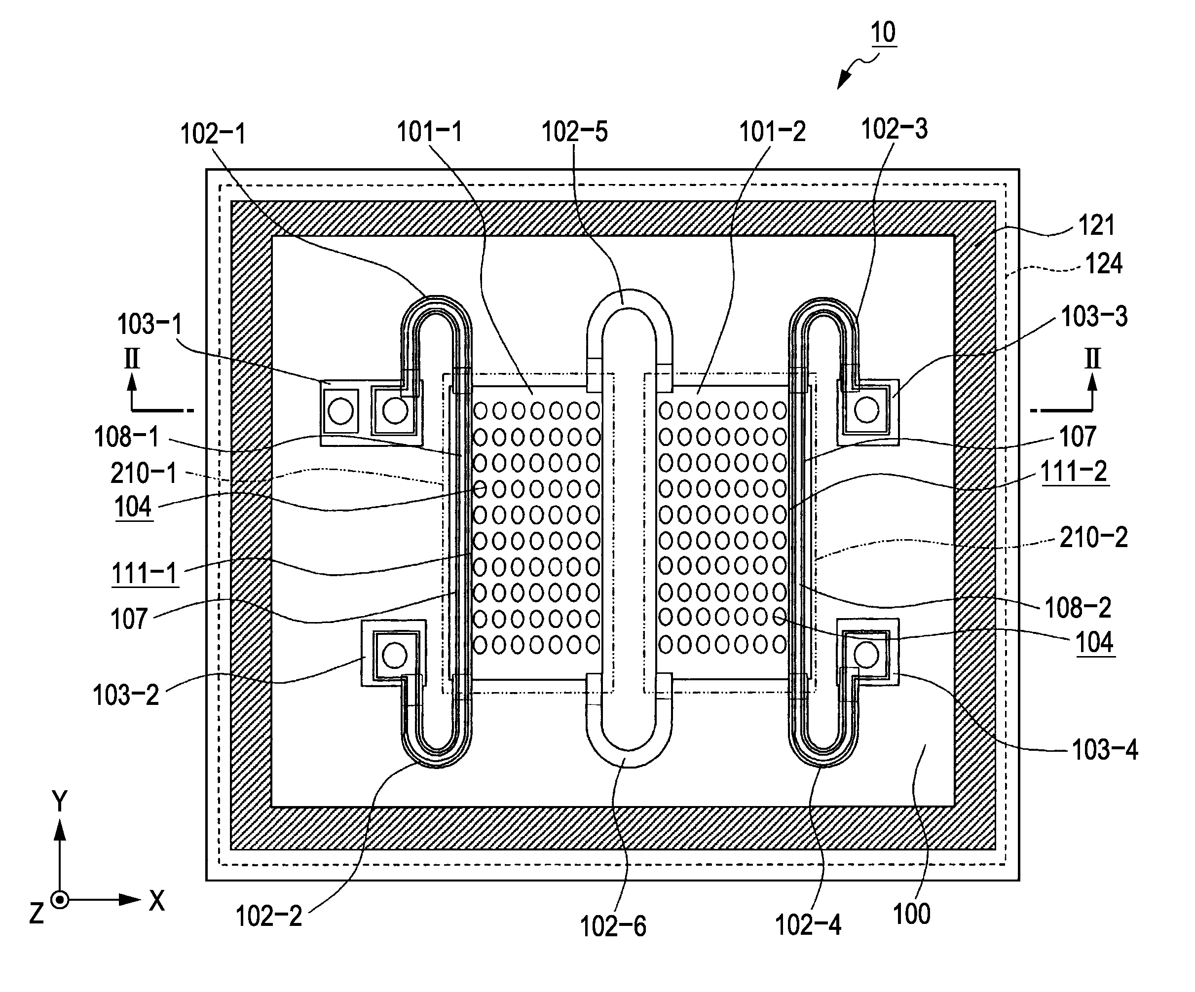
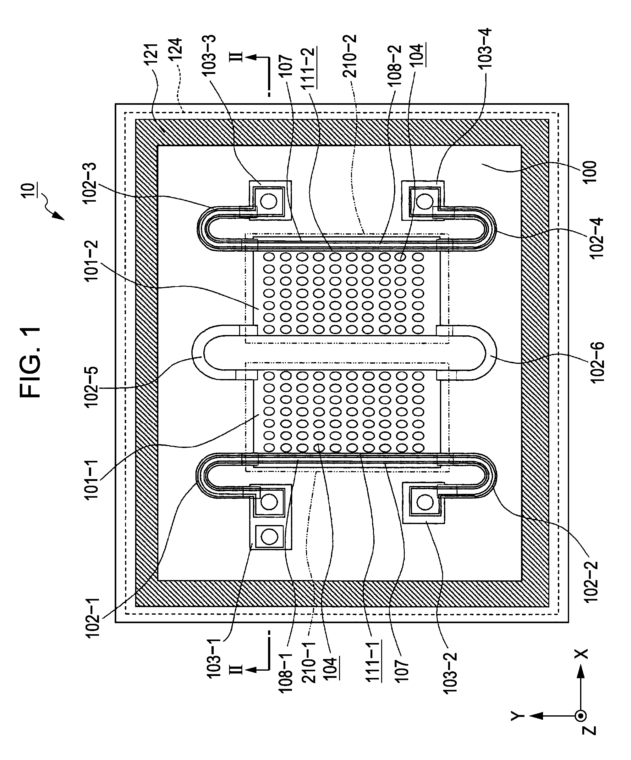
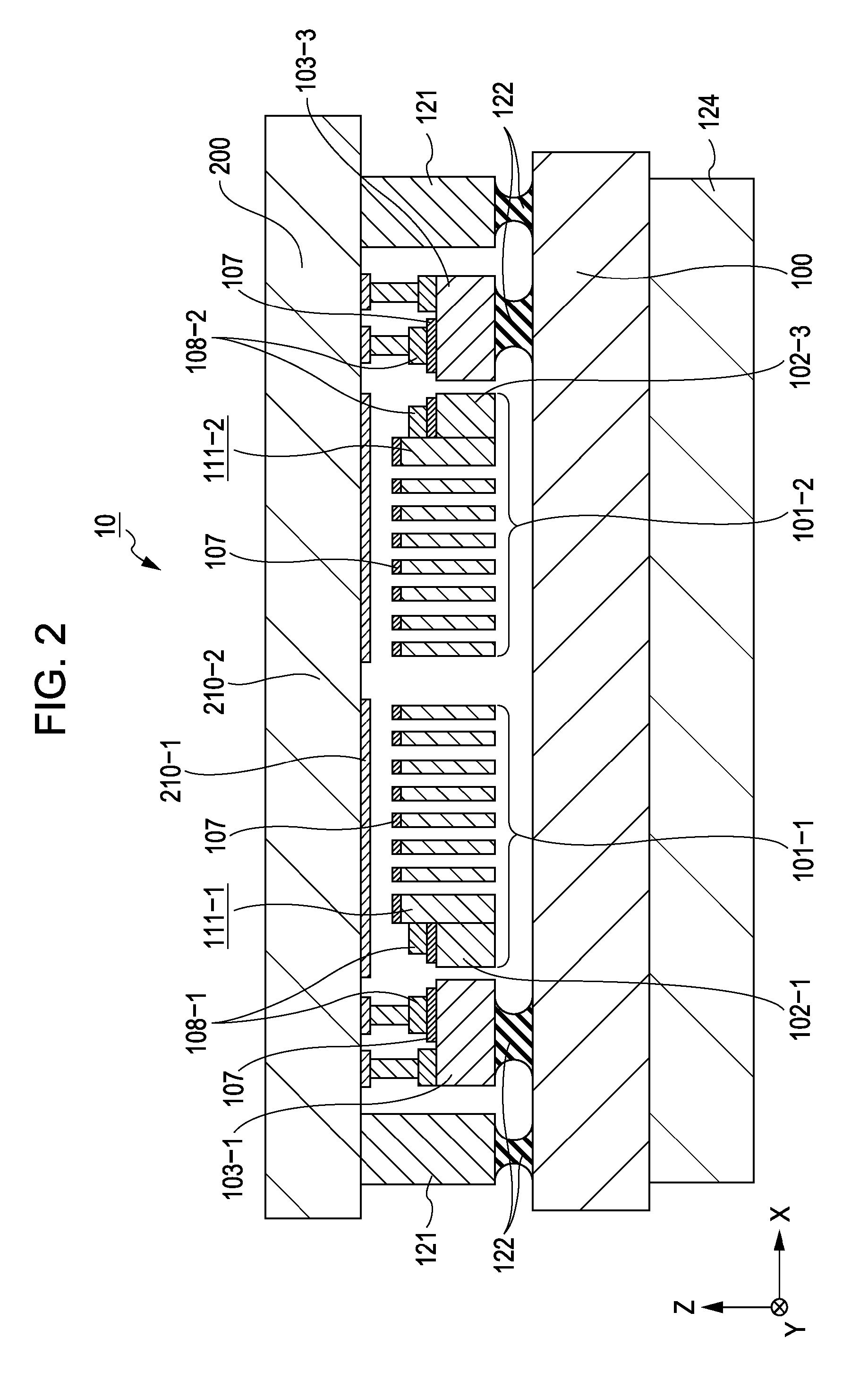
[0053] As shown in FIG. 3, the MEMS driving device according to the first embodiment includes a detecting unit 20 for detecting (monitoring) oscillation of oscillators (corresponding to the first and second oscillators 101-1 and 101-2 in FIGS. 1 and 2) of the MEMS sensor 10, and a feedback circuit 30 for amplifying a signal detected by the detecting unit 20 and inputting the amplified signal as a driving signal to the MEMS sensor 10.
[0054] As described above, the detecting unit 20 electromagnetically detects (monitors) the oscillation of the oscillators of the MEMS sensor 10. However, the detection principle of the detecting unit 20 is not limited to electromagnetic detection, but electrostatic detection, piezoelectric detection, or the like, may be used. In other words, any detecti...
second embodiment
[0079]FIG. 8 is a block diagram showing the configuration of a MEMS driving device according to a second embodiment of the present invention. In FIG. 8, portions identical to those shown in FIG. 8 are denoted by identical reference numerals.
[0080] As shown in FIG. 8, the MEMS driving device has a configuration having a driving system using a PLL circuit 40 in addition to the driving system using the feedback circuit 30 in the MEMS driving device according to the first embodiment. In this configuration, when the MEMS sensor 10 is activated, the feedback circuit 30 is used to allow the MEMS sensor 10 to be in self-oscillating.
[0081] As is well-known, the PLL circuit 40 includes a VCO, a phase comparator, and a loop filter. The detecting unit 20 starts to operate on the basis of a signal detected by the detecting unit 20 in a state in which driving by the feedback circuit 30 allows the MEMS sensor 10 to self-oscillate.
[0082] Specifically, the feedback circuit 30 starts to operate us...
example application
[0085] The MEMS sensor including the above-described MEMS sensor 10 is usable in, for example, an active sensor such as one of an angular acceleration sensor, an angular velocity sensor, and an angle sensor, or one of an acceleration sensor, a velocity sensor, a displacement sensor, and a jerk sensor. More specifically, the MEMS sensor including the above-described MEMS sensor 10 is usable in a sensor that needs reference oscillation, such as a gyroscope for measuring displacement by using the Coriolis force, or a sensor in which an increase in sensitivity is achieved by using reference oscillation and a carrier. The above-described MEMS driving devices according to the first and second embodiments are used with MEMS sensors and are suitable for use as driving devices for the MEMS sensors.
PUM
 Abstract
Description
Claims
Application Information
 - R&D
- Intellectual Property
- Life Sciences
- Materials
- Tech Scout
- Unparalleled Data Quality
- Higher Quality Content
- 60% Fewer Hallucinations
Browse by: Latest US Patents, China's latest patents, Technical Efficacy Thesaurus, Application Domain, Technology Topic, Popular Technical Reports.
© 2025 PatSnap. All rights reserved.Legal|Privacy policy|Modern Slavery Act Transparency Statement|Sitemap|About US| Contact US: help@patsnap.com


