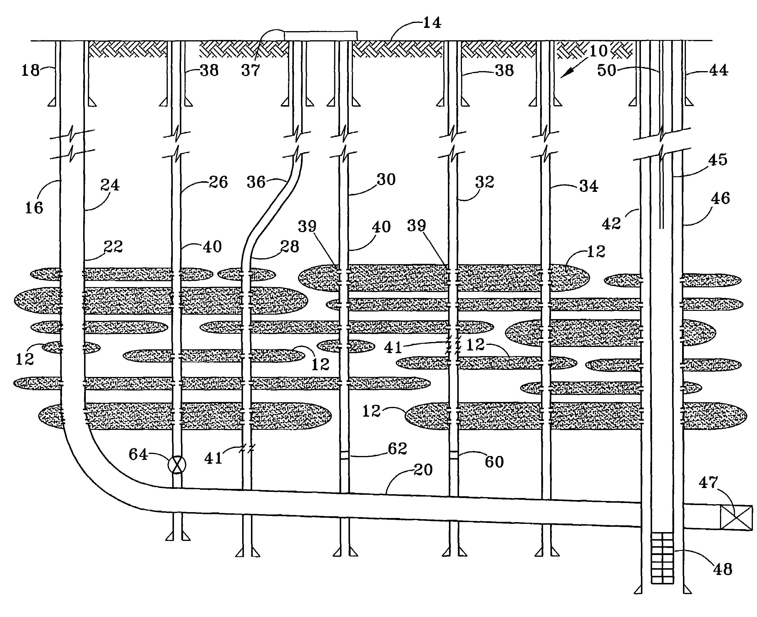
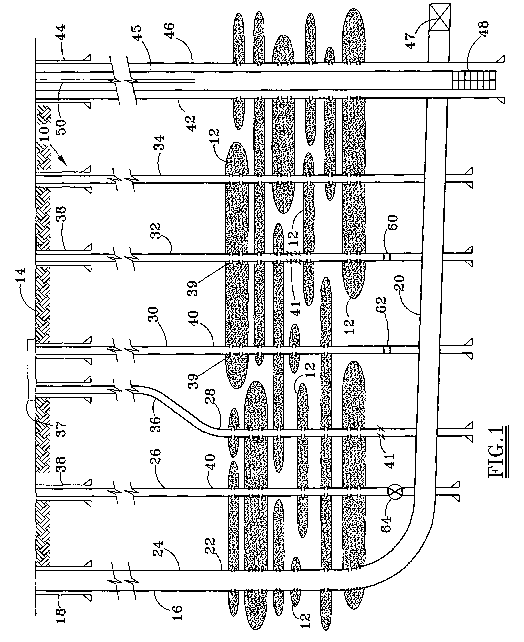
Problems with conventional technology for recovering subsurface hydrocarbons include lenticular pay zones which are relatively small and heterogeneous, and situations where reservoir quality in adjacent sand lenses targeted for a single frac stage vary considerably.
Pressure depletion may be higher in one zone, and fracture stimulation methodologies may be inefficient and largely ineffective because frac stages targeting multiple lenses may travel in a single interval with the highest depletion and lowest fracture gradient.
Even in situations where the reservoir quality and pressure in adjacent sand lenses targeted for a single frac stage are similar, current methods may yield limited fracture half-lengths in a
single zone and leave many zones under-stimulated due to constraints in pump rate and
fluid viscosity to avoid excess frac height growth.
Many wells encounter thin production sand stingers with an average thickness of from 5 to 20 feet, in which case it is not practical to complete all of the zones due to the need for fracture stimulation.
Wells must be substantially vertical if beam pump lift systems are used, so that field areas with difficult access roads and location issues cannot be economically exploited.
Paraffin deposition is problematic during the production phase, and there is a need to reduce development and lifting costs for effective production.
Frac treatments can also be problematic on initial completion because rock properties of sand and shales are similar.
Secondary
recovery with water injection from one well and recovery from another well for pressure maintenance and sweep generally are inefficient due to variabilities of rock properties and unknown continuity of sand lenses between wells.
Injection of water in offset wells targeting specific zones for pressure maintenance and oil sweep generally do not allow the operator to know if injected water has experienced premature breakthrough in the production zone, since all zones are commingled and only total water and water rates are measured.
Various problems nevertheless exist with respect to prior art approaches for utilizing existing technology to recover formation fluids.
The use of
production tubing with suitable bridge plugs or packer assemblies to isolate specific zones for swab testing involves expensive rig time.
Many times,
cement, water, or gas zones must be squeezed, and the sand in the
wellbore must be cleaned out and a swab test again performed, which is also rig time intensive and costly.
The inability to test production influx from specific zones during the production mode is also a problem, since all zones are typically commingled and produced with beam pump lift systems.
Paraffin deposition on rods and tubing in production wells is a significant problem since produced oil moves slowly toward the surface, and is cooled as it travels upward in the well.
High operating costs thus result from prior art techniques and equipment to recover subterranean formation fluids.
A number of challenges are commonly encountered when using a current exploitation approach, including:Significant completion times are required for swab testing and fracture
simulation using jointed tubing.Lenticular pay zones are often relatively small in size with heterogeneous rock properties and thus require companies developing such reserves to
drill wells on very small well spacings.
High well densities are often required to
exploit the multitude of relatively small sand lenses or reservoir compartments which may be very costly.
When viewed in aggregate, the multiple stacked reservoirs may contain significant oil in place, but when only a single reservoir compartment is completed for production, the development may be uneconomic.
Offshore or
land development where surface constraints do not allow a
high density of well development are not practical due to the need for a dedicated beam pump
artificial lift system.Many wells encounter thin production sand stingers with an average thickness of from 5 to 20 feet, in which case it is not practical to complete all of the zones due to the need for fracture stimulation.
Many thin zones are deemed too marginal to perforate and stimulate using current completion practices.In situations where reservoir quality in adjacent sand lenses targeted for a single fracture stimulation stage vary considerably or where pressure depletion is higher in one zone, current fracture stimulation methodologies may be inefficient and largely ineffective because fracture stages targeting multiple lenses will go in the single interval with the highest depletion / lowest fracture gradient.In situations where the reservoir quality and pressure in adjacent sand lenses targeted for a single fracture stage are similar, current stimulation methods may yield limited fracture half-lengths in a
single zone and leaves many zones under-stimulated due mainly to constraints in pump rate and
fluid viscosity to avoid excessive fracture height growth.Secondary recovery with water, gas, and / or
steam injection from one well and recovery from another well for pressure maintenance and sweep generally are inefficient due to: (1) variability of rock properties, and (2) unknown continuity of sand lenses between wells.Petrophysical evaluation through log analysis is complicated due to: (1) variations in
lithology, (2) variable and extremely low water salinities, and (3) unknown fluid invasion profiles.Many thin zones will be deemed too marginal to perforate and stimulate due to the relatively high cost of completion.Wells must be substantially vertical if beam pump lift systems are used, thus field areas with difficult access road and location issues or in many offshore environments cannot be economically exploited.Currently available methods do not allow one to test oil and
water productivity per zone while producing the commingled sand / shale sequences with beam pump lift systems.
Injection of water, steam, and / or gases in offset wells targeting specific zones for pressure maintenance and oil sweep generally do not allow the operator to know if injected water has experienced premature breakthrough in the completed zone of the production wells, since all zones are commingled and only total water and total
hydrocarbon rates are measured.
Current completion and production approaches in these oilfield development situations require expensive and
time consuming rig intervention using a swab testing procedure in an attempt to ascertain which zones yield excessive water, steam, and / or gas.In many oilfields, paraffin deposition inside the
production tubing and on the exterior of rod strings in production wells is problematic during production phase.
As the
crude oil moves relatively slowly up the tubing string towards the surface, the oil cools which contributes significantly to the problem.
Removing such paraffin from downhole tubing and rod strings is a costly problem in many such oilfield developments.Paraffin deposition on rods and tubing in production wells is a significant problem since produced oil moves slowly toward the surface, and is cooled as it travels upward in the well.
Various problems nevertheless exist with respect to prior art approaches for utilizing existing technology to recover formation fluids.
High operating costs thus result from prior art techniques and equipment to recover subterranean formation fluids.


