
Reconfigurable user interface systems

a user interface and reconfigurable technology, applied in the field of touch screen user interface systems, can solve the problems of inability to adapt to individual users, standardized and not tailored to individual users, and the operation of touch screen by direct manipulation can generate an unacceptable risk of errors, and achieve the effect of repositioning such tactile key modules

Active Publication Date: 2008-11-18
NCR CORP
View PDF15 Cites 71 Cited by
  • Summary
  • Abstract
  • Description
  • Claims
  • Application Information

AI Technical Summary

Benefits of technology

[0008]In another embodiment, the present invention provides a method of producing a user interface system for inputting information comprising a touch screen and a tactile key having a tactile surface. The method comprises placing the tactile key adjacent to a touch screen actuator within the touch screen, such that manipulation of the tactile surface is detectable by the touch screen actuator. The method may include mapping the function of the tactile key through the touch screen actuator to a program for execution of the function. The tactile key may be secured in a fixed position adjacent to the touch screen actuator. Alternatively, it may be positioned in a manner so that it can be readily repositioned adjacent to a different touch screen actuator.

Problems solved by technology

One major disadvantage of such hardware systems, however, is that the keyboard layouts are either permanent, or are cumbersome and expensive to reconfigure.
Hence, these systems generally are standardized and not tailored to individual users.
Where accuracy is critical, operation of a touch screen by direct manipulation can generate an unacceptable risk of errors.
Hence, the accuracy with which a user touches a location with the requisite contact pressure required to actuate one selected graphic object out of many displayed on the same touch screen cannot be controlled by the touch screen itself.
As a result, a finger carelessly applied to a portion of the touch screen adjacent to an intended portion selected, can result in erroneous data entry, double data entry, or in data non-entry.
In addition, where an operator is handicapped, or has the task of operating a touch screen over an extended time period, direct manipulation can lead to errors caused by fatigue, impatience, inattentiveness and other human factors.
These problems also lead to slow data input speeds, as the typical operator attempts to exercise care to minimize errors.

Method used


Image

  • Reconfigurable user interface systems
  • Reconfigurable user interface systems
  • Reconfigurable user interface systems

Examples


Embodiment Construction

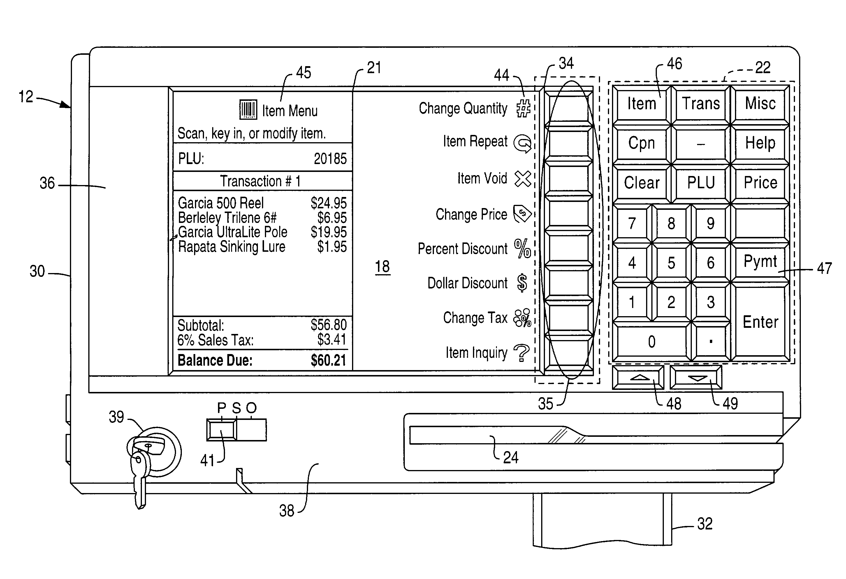
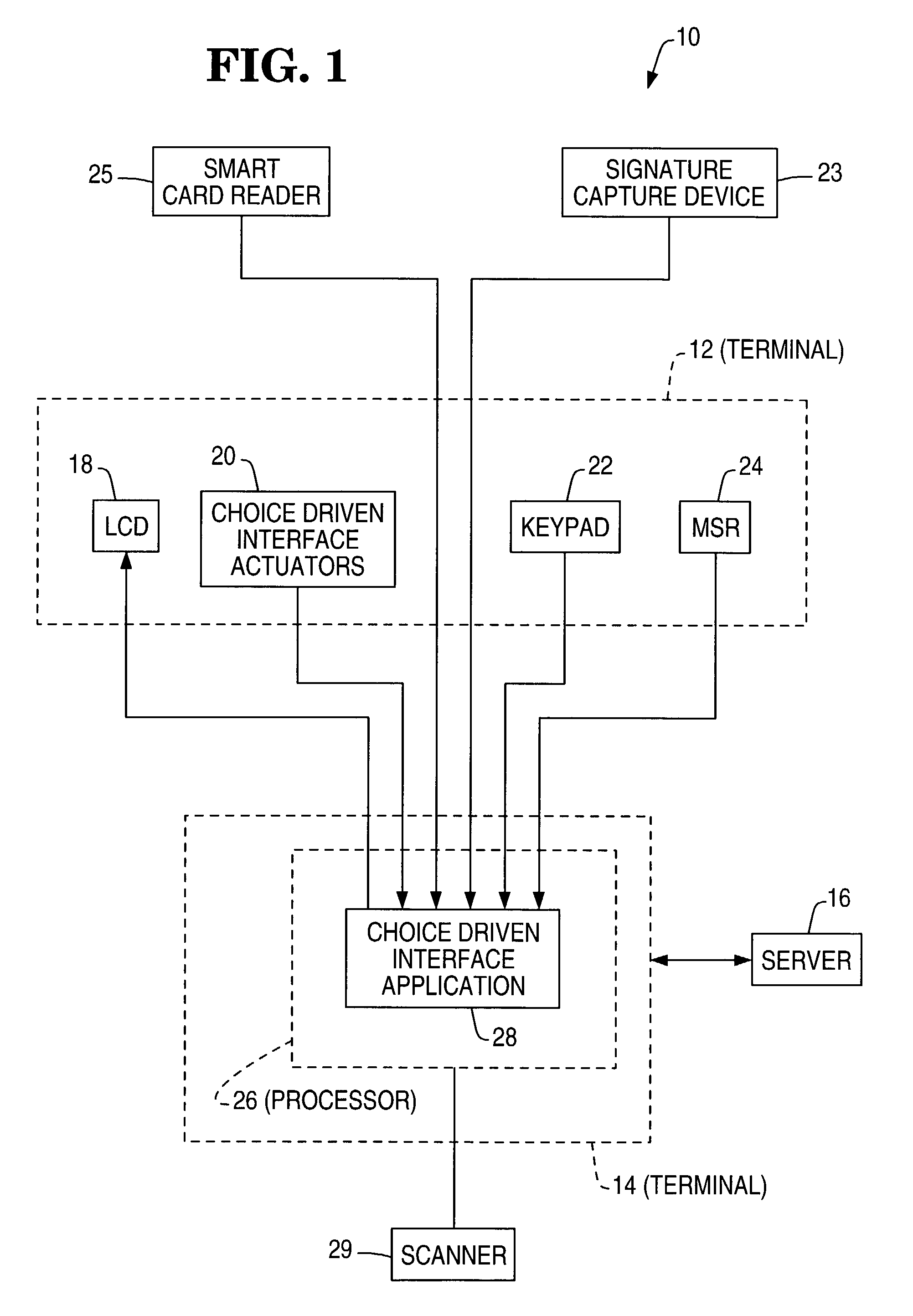
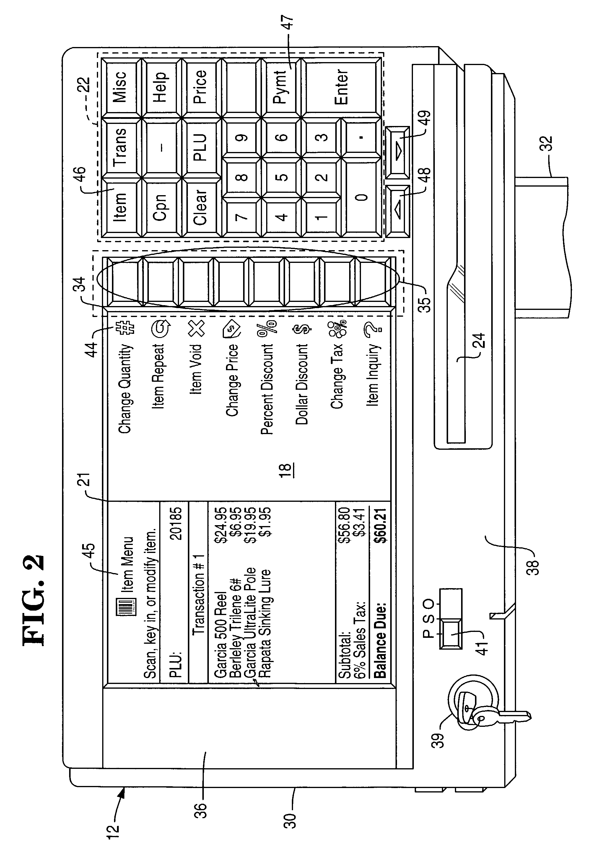
[0035]According to one aspect of the present invention, a software upgrade kit and one or more key modules can be readily utilized to add additional key capacity to an existing point of sale (POS) or other terminal having a touch screen user interface, such as an NCR DynaKey™ POS device. Further details of such systems are found, for example, in U.S. Pat. No. 6,002,395 and 5,920,312 which are incorporated by reference herein in their entirety. See also U.S. Pat. No. 6,411,286 which is also incorporated by reference herein in its entirety. While the present invention is described in the context of such terminals, it will be recognized that the present teachings can be adapted to various touch screen based terminals to provide a high degree of design and user flexibility in a cost effective manner, as addressed in greater detail below.

[0036]FIGS. 1-4 show exemplary embodiments of a touch screen user interface system which may be suitably modified to implement the present invention as ...


PUM


Abstract

User interface systems comprising a touch screen actuator and a tactile key, in which the tactile key is placed adjacent to the touch screen actuator so that manipulation of the tactile key can be detected by the touch screen actuator. Tactile key modules that can be so placed adjacent to a touch screen actuator, and methods of producing such user interface systems, as well as, repositioning such tactile key modules, are also described.

Description

FIELD OF THE INVENTION[0001]The present invention relates to improvements in the field of touch screen user interface systems. In particular, the present invention relates to reconfigurable touch screen systems augmented by dynamic or static tactile keys that provide signaling action, detectable by touch screen actuators, with improved accuracy and ease of use.BACKGROUND OF THE INVENTION[0002]Traditional user interface hardware systems such as tactile keyboards typically are actuated by applying pressure to a selected key, which then causes the actuation of further components within the keypad or keyboard. The key to which such pressure is applied generally is a discrete hardware element, and the key can readily be designed to require the application of a pressure exceeding a threshold level for its actuation. As a result, the discrete hardware keys in such systems foster accurate data entry at high speeds. One major disadvantage of such hardware systems, however, is that the keyboa...

Claims


Application Information

Patent Timeline
IPC IPC(8): G06F3/041
CPCG06F3/04886
Inventor POYNTER, WILLIAM DOUGLAS
Owner NCR CORP
Learn More