Cooling structure of electric device

a technology of cooling structure and electric device, which is applied in the direction of indirect heat exchangers, dc-ac conversion without reversal, light and heating apparatus, etc., and can solve the problem that the performance of the second electric device is not affected

Active Publication Date: 2008-11-18
TOYOTA JIDOSHA KK
View PDF35 Cites 19 Cited by
  • Summary
  • Abstract
  • Description
  • Claims
  • Application Information

AI Technical Summary

Benefits of technology

[0010]It is an object of the invention to provide a cooling structure of an electric device, which is capable of cooling a plurality of electric devices effectively while reducing its size.
[0012]In the aforementioned invention, the cooling medium is circulated for cooling the first and the second electric devices. The first holding member holds the first electric device so as to be positioned downward of the cooling passage. The second holding member holds the second electric device so as to be positioned upward of the cooling passage. As a result, the single cooling passage may be provided for cooling those first and the second electric devices with the cooling medium that flows therethrough. Accordingly there is no need of providing the cooling passages independently for the first electric device and the second electric device. The first electric device that generates larger heating value than that of the second electric device is disposed downward of the cooling passage. Meanwhile the second electric device that generates smaller heating value than that of the first electric device is held upward of the cooling passage. In the case where the cooling medium evaporates to generate bubbles, those bubbles move upward of the cooling passage. Accordingly, bubbles are hardly generated around the first electric device that needs to be cooled more than the second electric device. Even if the bubbles gather around the second electric device that generates smaller heating value than that of the first electric device, they hardly influence the performance of the second electric device. The cooling structure is capable of effectively cooling a plurality of electric devices while reducing its size.
[0014]In the aforementioned invention, the recess portion formed in the upper surface of the first holding member allows the cooling medium to flow thereinto. The second holding member seals the recess portion from above. The cooling passage may be defined by the first and the second holding members. As the cooling medium becomes directly in contact with the first and the second holding members, the heat may be efficiently absorbed by the cooling medium.
[0016]In the aforementioned invention, a plurality of cooling fins project upward from the bottom of the recess portions. This may increase the area of the first holding member in contact with the cooling medium by the amount corresponding to the number of the cooling fins. Accordingly, the heat may be efficiently absorbed by the cooling medium.
[0018]In the aforementioned invention, the first electric device is formed as the inverter. In the case where the vehicle is equipped with a driving battery and a three-phase motor, the inverter serves to convert the electric current supplied from the driving battery from direct current into alternating current so as to be supplied to the three-phase motor. In order to drive the three-phase motor, that is, start the vehicle, the inverter is always operated. The second electric device may be formed as at least one of the condenser and the converter. The condenser functions in storing electric charge temporarily for smoothing. Generally, the heating value of the condenser is smaller than that of the inverter. Meanwhile the converter functions in boosting the electric power supplied from the driving battery to be supplied to the three-phase motor so as to be driven at a desired output in response to the vehicle running state or the acceleration request from the vehicle operator. There may be a case that the converter has not been operated even if the three-phase motor is driven. The heating value of the converter, thus, is smaller than that of the inverter. The aforementioned inverter is held downward of the cooling passage, and at least one of the condenser and the converter is held upward of the cooling passage. The above arrangement makes it possible to cool the inverter and at least one of the condenser and the converter efficiently.

Problems solved by technology

Even if the bubbles gather around the second electric device that generates smaller heating value than that of the first electric device, they hardly influence the performance of the second electric device.

Method used


Image

  • Cooling structure of electric device
  • Cooling structure of electric device
  • Cooling structure of electric device

Examples


embodiment 1

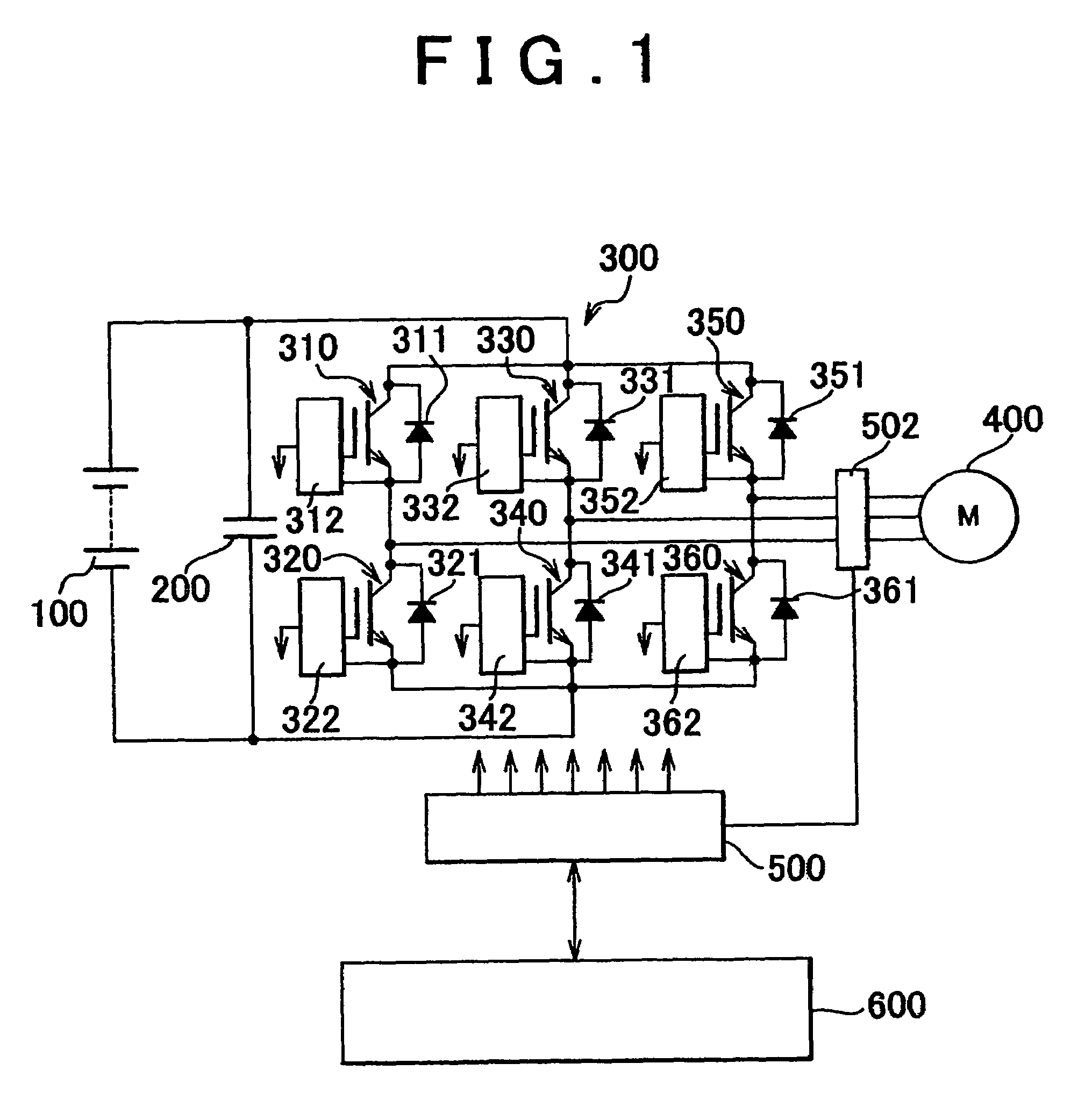
[0025]Referring to FIG. 1, a vehicle equipped with a cooling structure of a PCU having electric devices according to an embodiment 1 includes a driving battery 100, a filter condenser 200, an inverter 300, a driving motor 400, a signal generation circuit 500, and a control circuit 600.

[0026]The driving battery 100 is a combination battery formed by connecting a plurality of battery modules each formed of a plurality of cells connected in series. The driving battery 100 has a voltage value of, for example, about 300 V.

[0027]The filter condenser 200 is connected in parallel with the driving battery 100. The filter condenser 200 temporarily stores the electric charge to smooth the electric power supplied from the driving battery 100. The electric power smoothed by the filter condenser 200 is supplied to the inverter 300.

[0028]The inverter 300 includes six IGBTs (Insulated Gate Bipolar Transistor) 310 to 360, six diodes 311 to 361 each connected in parallel with the respective IGBT so a...

embodiment 2

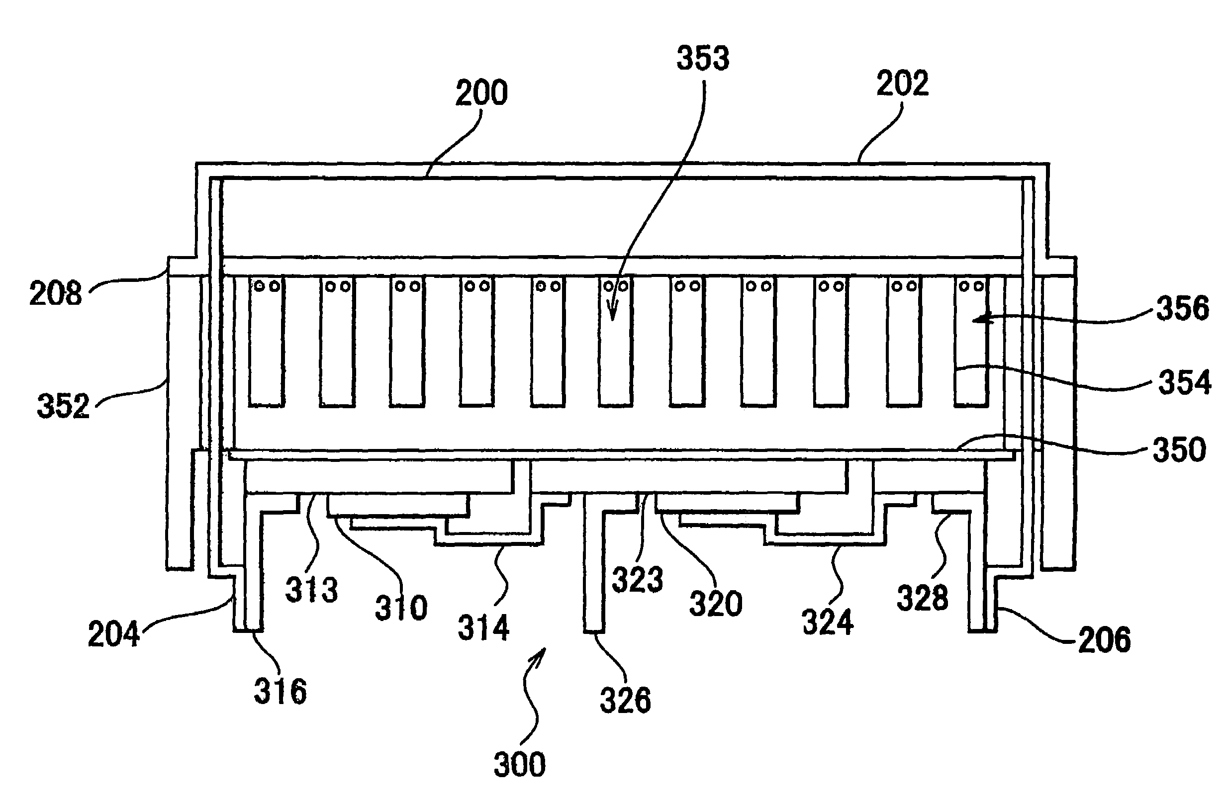
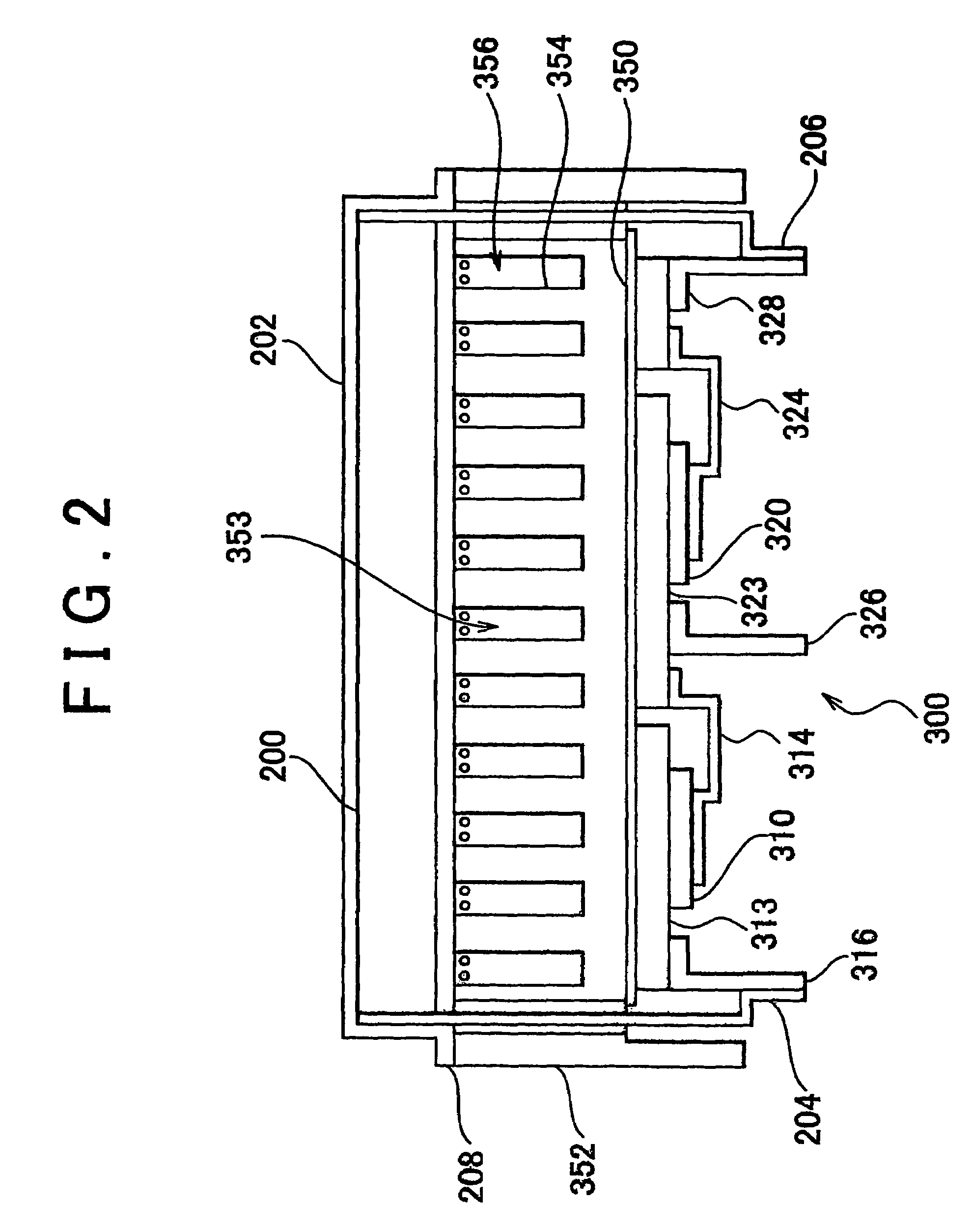
[0046]An explanation with respect to a PCU having a cooling structure of electric devices according to an embodiment 2 will be described referring to FIG. 3. The PCU according to the embodiment includes a converter 700 held upward of the cooling passage 356 in place of the condenser 200 as described in the embodiment 1. Other structures and functions of this embodiment are the same as those of the embodiment 1. Accordingly no further detailed explanation of those structures and functions will be described herein.

[0047]FIG. 3 is a sectional view of the PCU according to this embodiment. The converter 700 is held in a converter case 702. A positive electrode of the converter 700 is connected to the positive electrode terminal 316 of the inverter 300 via a positive electrode bus bar 704. A negative electrode of the converter 700 is connected to the negative electrode terminal 328 via a negative electrode bus bar 706.

[0048]An opening of the recess portion 353 is coverd with the lower sur...

embodiment 3

[0051]An explanation with respect to a PCU with a cooling structure of electric devices according to an embodiment 3 will be described referring to FIG. 4. In the PCU of the embodiment according to the invention, the condenser 200 in the embodiment 1 is not held upward of the cooling passage 356, but a seal plate 800 serves to seal the opening of the recess portion 353. Other structures and functions of this embodiment are the same as those of the embodiment 1. Accordingly no further detailed explanation of those structures and functions will be described herein.

[0052]FIG. 4 is a sectional view of the PCU according to the embodiment 3. The seal plate 800 includes a plurality of projections 802 formed on the upper surface of the seal plate 800. The opening of the recess portion 353 is covered with the lower surface of the seal plate 800. The space defined by the inverter case 352, cooling fins 354, and the seal plate 800 allows the cooling water to flow therethrough. That is, the coo...


PUM


Abstract

A cooling structure of electric devices in a vehicle is structured to hold an inverter (300) downward of a cooling passage (356), and to hold a condenser (200) upward of the cooling passage (356). The heating value generated by the inverter (300) is larger than the heating value generated by the condenser (200).

Description

[0001]This is a 371 national phase application of PCT / IB2004 / 003659 filed 9 Nov. 2004, claiming priority to Japanese Patent Application No. 2003-388069 filed 18 Nov. 2003, the contents of which are incorporated herein by reference.INCORPORATION BY REFERENCE [0002]The disclosure of Japanese Patent Application No. 2003-388069 filed on Nov. 18, 2003 including the specification, drawings and abstract is incorporated herein by reference in its entirety.BACKGROUND OF THE INVENTION[0003]1. Field of Invention[0004]The invention relates to a cooling structure of an electric device, and more particularly, to a cooling structure of a plurality of electric devices.[0005]2. Description of Related Art[0006]Coping with recent environmental issues, development of hybrid vehicles using driving force of the motor, fuel cell vehicles, electric vehicles and the like have been increasingly focused. The vehicle of the aforementioned type is generally equipped with a PCU (Power Control Unit) that regulate...

Claims


Application Information

Patent Timeline
Patent Type & Authority Patents(United States)
IPC IPC(8): H05K7/20F28D15/00H02M7/00H02M7/48H05K7/14
CPCH05K7/20927H02M7/003H05K7/14H05K7/20
Inventor OHNISHI, KENICHITORII, KOSHI
Owner TOYOTA JIDOSHA KK
Why Eureka
Try Eureka