Manual tensioner for non-metallic straps

a non-metallic strap and tensioner technology, applied in the field of manual tensioners, can solve the problems of not being able unable to incorporate very cumbersome slack reduction mechanisms, user cannot pull an end of the strap to manually remove excess slack, etc., to achieve the effect of reducing strap slippage and milling, facilitating slack removal, and great downward normal for

Active Publication Date: 2008-11-25
SIGNODE IND GRP
View PDF9 Cites 10 Cited by
  • Summary
  • Abstract
  • Description
  • Claims
  • Application Information

AI Technical Summary

Benefits of technology

[0016]A user presses the lever down to drive the gear system and to begin tensioning the strap around the load. The lever generally pivots about a point near the proximal end of the tensioner and has a gripping portion or distal end that is in proximity to a distal end of the tensioner. According to a first embodiment of the invention, the tensioner incorporates a double gear system, which allows the strap to be tensioned in a clockwise direction around the load. In other words, the strap is tensioned or pulled toward a distal end of the lever and the tensioner, which results in the tensioner and feed wheel applying a greater downward normal force to the strap. Unlike prior art tensioners, the feed wheel effectively presses down on the strap when the strap is tightly wound around the load. Thus, strap slippage and milling are reduced and, in many instances, are completely eliminated. According to a second embodiment of the invention, the tensioner incorporates a selective locking mechanism to facilitate slack removal. The selective locking mechanism includes a ring-pawl assembly and a groove formed on the shaft. The ring-pawl assembly includes a ring that presses the pawl down against the shaft, and the shaft couples the feed wheel to the tension gear. An upper portion of the pawl interlocks with a notch formed in the tension gear. A lower portion of the pawl cooperates with the groove formed in the shaft. The pawl and grooves are shaped to permit the shaft to rotate in one direction with respect to the pawl, while the pawl remains stationary. Thus, when a user pulls the strap to remove excess slack, the feed wheel rotates, which causes the shaft to rotate. Because the shaft may rotate without causing the pawl to rotate, the tension gear, which is interlocked with the pawl, remains stationary when slack is removed from the strap and the shaft rotates. The user can, therefore, tighten the strap around the load in a shorter time by manually removing excess slack before tightening the strap around the load using the tensioner.
[0017]According to a third embodiment of the invention, a gearbox of the tensioner can be disassembled so that the gears and / or feed wheel are easily accessible. According to a fourth embodiment of the invention, a spring used to apply a downward force on the feed wheel and the strap is positioned outside the gear box, reducing the number of parts and complexity of the gear box. As a result, the gear box and parts within can be disassembled and reassembled with greater ease.
[0018]According to a fifth embodiment of the invention, a sealing flange protrudes upward from a cutting block body, creating space between the load and the upper and lower strap layers. As a result, a sealing clip can be applied so that the arms of the sealing clip depend below the strap. The arms can then easily be crimped around the bottom strap, instead of potentially crushing the edge of the strap if the cutting block were flat, as in prior art tensioners.
[0019]According to a sixth embodiment of the invention, a cutting blade is positioned at a proximal end of the tensioner. The cutting blade is activated by turning the lever of the tensioner toward a proximal end of the tensioner a predetermined number of radians to a cutting point, when a portion of the lever contacts the cutting blade assembly. The lever is turned beyond the cutting point and urges the cutting blade down to cut the strap. By positioning the cutting blade at the front of the tensioner, it remains easy to utilize the cutting blade for cutting purposes while reducing inadvertent, premature strap cuts, which were prevalent in tensioners incorporating cutting blades positioned toward a distal end of the tensioner.

Problems solved by technology

Non-metallic hand held tensioners of the art are able to tighten the strap around the load, but they suffer from many shortcomings.
However, prior art tensioners used with non-metallic straps incorporate gear box assemblies that either did not allow for manual slack reduction or incorporated very cumbersome slack reduction mechanisms.
In other words, after the strap is wrapped around the load and fed into the tensioner, the user either cannot pull an end of the strap to manually remove excess slack or cannot remove excess slack without exerting great effort.
As a result, the strap may slip from the feed wheel and / or the feed wheel may mill or shear top portions of the plastic strap off.
Applying the additional downward force will prematurely tire the user.
As a result, the strap may slip within the gripper and / or mill or be sheared by the gripper.
This also causes milling.
Further, tensioners using windlasses require greater forces to tighten the strap around the load, the tighter the strap is wound around the load.
However, the bottom and top strap layers often lay flush against the load, causing the arms of the sealing clip to abut the edges of the strap layers instead of depending below them.
As a result, a user often inadvertently crushes the edges of the strap when crimping the arms of the clip.
Many known tensioners include cutters to cut the strap, but the cutters are difficult to use.
Some cutters require the user to completely remove the tensioner from the sealed strap, and others increase the risk of inadvertently cutting the strap before the seal is applied.
The problem is that the lever is also pushed down to tighten or tension the strap around the load, and a great deal of force must be applied to the lever to tighten the strap.
Thus, the lever can be inadvertently pushed down beyond the breaking point before the seal is applied, causing the blade to prematurely cut the strap.
Tensioners of the art also were manufactured from one piece gearboxes that made disassembly very cumbersome and difficult.
In addition, the gear box assembly incorporated springs that acted against various gearbox components, also making disassembly and reassembly of the gear box difficult.

Method used


Image

  • Manual tensioner for non-metallic straps
  • Manual tensioner for non-metallic straps
  • Manual tensioner for non-metallic straps

Examples


first embodiment

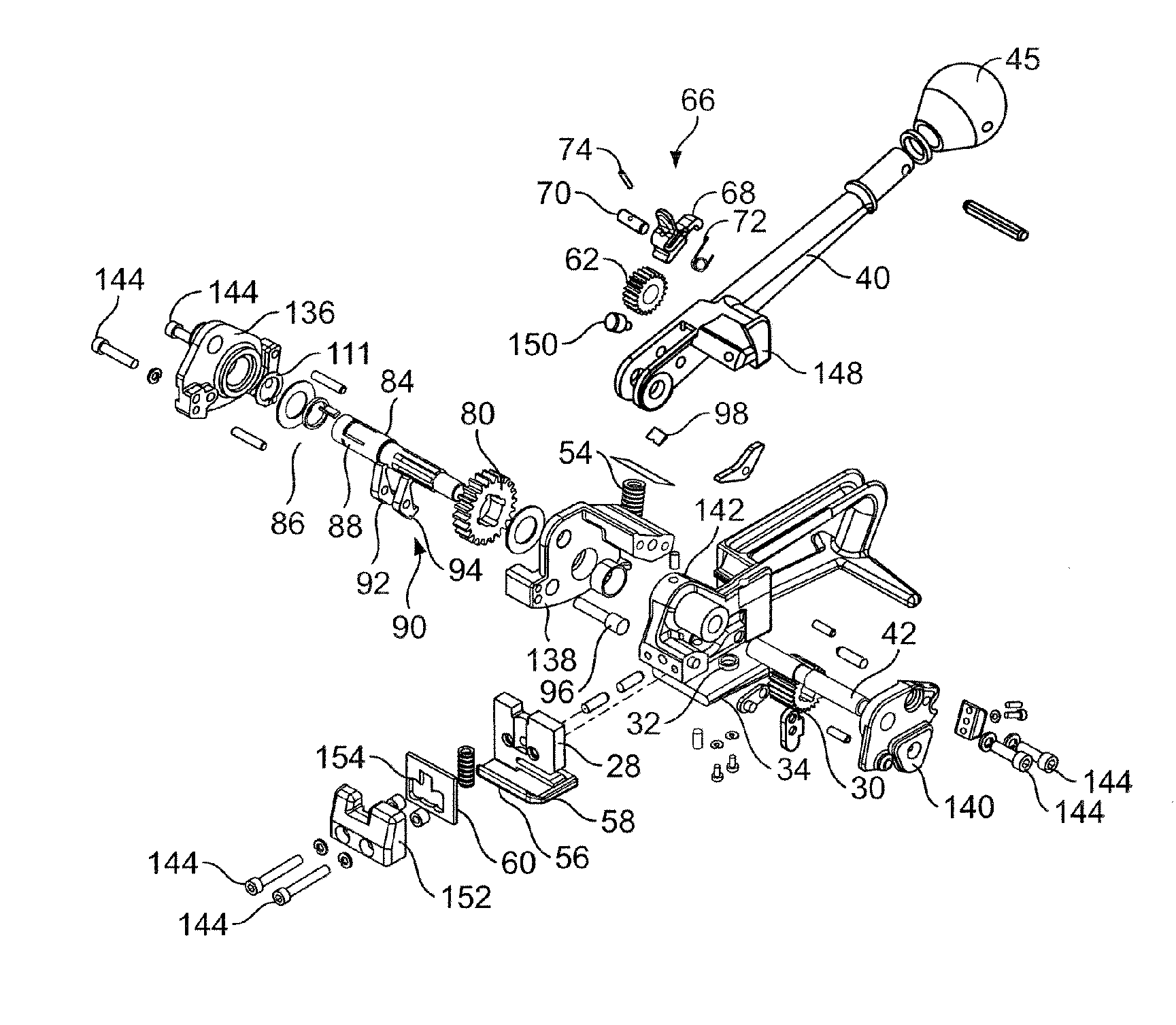
[0036]FIG. 3 shows a disassembled view of a tensioner incorporating several aspects of the invention. In the invention, a drive gear 62 is rotatively mounted to the lever 40 so that, when the lever is pressed down (in the direction of arrow 47), the drive gear rotates in a clockwise direction in the direction of arrow 64 (FIG. 4). In a specific embodiment, the drive gear locking mechanism 66 shown in FIG. 4 is used. The drive gear locking mechanism 66 includes a drive pawl 68, pawl pin 70, drive pawl spring 72 and a roll pin 74. The drive gear locking mechanism 66 prevents the drive gear 62 from turning counter-clockwise when, for example, the lever is pulled up, in the direction of arrow 49. Those of skill in the art will appreciate that other types of drive gear locking mechanisms may also be employed.

[0037]Teeth 76 of the drive gear 62 are interlocked with teeth 78 of a tension gear 80 so that, when the drive gear 62 rotates clockwise, the tension gear 80 turns counter-clockwise ...

second embodiment

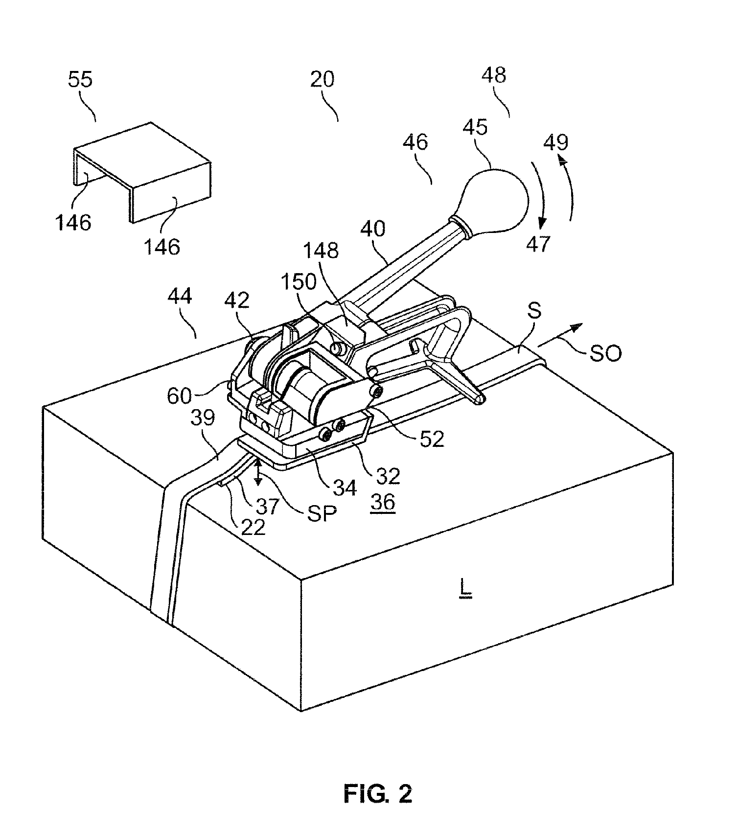
[0042]Pursuant to the invention, a selective locking mechanism 104 is employed to permit a user to remove slack from the strap. In particular, a user may manually pull the strap S (toward arrow 50 in FIG. 2) to remove excess slack. This causes the feed wheel 30 and the shaft 84 to turn counter-clockwise (in the direction of arrow 82 in FIG. 4). By employing the selective locking system 104, the tension gear 78 and, thus, the drive gear 76 and lever 30, will not move. This reduces the amount of effort that would be necessary to manually remove slack and permits a user to remove a majority of the slack by simply pulling the strap S. Additional desired tension may be achieved by pushing the lever down a minimal number of times.

[0043]In the specific embodiment shown in FIG. 5, the selective locking mechanism 104 includes a pawl-ring assembly 86 and shaped grooves 88 formed on the shaft 84. The pawl-ring assembly 86 includes a ring 106 that pushes the pawl 108 onto the shaft 84. In one e...

third embodiment

[0048]Pursuant to the invention shown in FIG. 3, a gear box 52 assembly includes left, middle and right gear box housing members 136,138, 140. The left and middle members 136, 138 are coupled to one another and to a base plate 142 by removable fasteners 144. The base plate 142 extends upwardly from the base 34. The right member 140 is coupled to the middle housing member 138 by removable fasteners 144. The tension gear 80 is housed between the left and middle members 136, 140, and the feed wheel 30 is housed between the right and middle members 140. Easier access to the tension gear and feed wheel is accomplished by allowing a user to disassemble the gear box 52 by removing the removable fasteners 144.


PUM

PropertyMeasurementUnit
non-metallicaaaaaaaaaa
obtuse angleaaaaaaaaaa
tensionaaaaaaaaaa

Abstract

A tensioner is disclosed for applying a non-metallic strap around a load. The tensioner includes a base and a lever that can pivot. A drive gear is mounted to the lever and rotates clockwise. A tension gear engages the drive gear and rotates counter-clockwise. A feed wheel is coupled to the tension gear and rotates counter-clockwise. A gripper is attached to the base. The strap is held stationary by the gripper, wrapped around the load, is fed underneath and is in contact with the feed wheel. When the lever is rotated down, the feed wheel rotates counter-clockwise. The strap is pulled toward a distal end of the tensioner and is tensioned in a clockwise direction around the load.

Description

BACKGROUND OF THE INVENTION[0001]The present invention relates to a manual tensioner with a cutter that may be used to apply a non-metallic strap around a load and to cut the strap from a strap supply.[0002]Straps are wrapped around loose objects, such as lumber, to bind the objects together. Straps are also wrapped around boxes and other items to package and secure the boxes and items together. Straps of different materials are often used to tighten different types of loads. For example, plastic straps are often used to tighten lumber loads and boxes. Tensioners are used to tighten or tension the straps around the load. Further, there are tensioners designed for metallic straps and others for plastic or non-metallic straps. A hand-held or manual tensioner is typically used when a load is to be tightened in the field, such as the one shown in FIG. 1.[0003]Non-metallic hand held tensioners of the art are able to tighten the strap around the load, but they suffer from many shortcoming...

Claims


Application Information

Patent Timeline
Patent Type & Authority Patents(United States)
IPC IPC(8): B21F9/00
CPCB65B13/025
Inventor CRITTENDEN, DAVID E.FIGIEL, JANUSZFREEMAN, MICHAEL W.
Owner SIGNODE IND GRP
Why Eureka
Try Eureka