Motorized self-winding reel for divers

a motorized, self-winding technology, applied in special-purpose vessels, underwater equipment, transportation and packaging, etc., can solve the problems of reducing the ability of divers, distracting and counter-productive, and less line can be stored on the reel

Inactive Publication Date: 2008-11-25
KALETA DENNIS ALFRED
View PDF12 Cites 14 Cited by
  • Summary
  • Abstract
  • Description
  • Claims
  • Application Information

AI Technical Summary

Benefits of technology

[0017]In accordance with the present invention, a motorized, self-winding diver's reel comprises a reel that holds a predetermined length of safety guide cord to be used by a scuba diver, an attaching device at the distal end of the safety guide cord for attachment to an anchor line (or boat), a cord tension sensor and circuit to turn an associated motor “on” and “off”, and a battery-powered electric motor housing in a waterproof compartment, to allow for a length of safety guide cord to pay out while moving away from the anchor point, and also automatically reeling in the slack cord that is created while moving toward the anchor point, thus maintaining a direct guideline return to this point.
[0018]An object of the present invention is to provide a line leveler for even distribution of the line over the entire reel to prevent tangling of the line, thus allowing for more line to be wound on the reel.
[0020]Another object of the present invention is to provide divers with a way to keep both hands free when returning to their point of origin.
[0021]In brief, a guide line reel is connected by gears to a battery-driven electric motor contained in a water-tight housing. The housing clips onto the gear of a diver by means of, for example, a D-ring connected to the diver's equipment, such as a buoyancy compensator device. The exposed end of the guide line clips onto an anchor point (e.g., the diver's point of origin). When the diver is swimming back to the point of origin, the tension on the line is released, causing a tension sensing mechanism on the housing to activate the motor and wind the guide line onto the guide line reel, removing any slack in the line, thereby keeping the diver on a direct course back to the point of origin. When the diver is moving away from the point of origin, the diver may loosen the drag on the reel to allow the line to unreel easily with the sensor disengaged and may engage the sensor and disengage the sensor as line is needed to be reeled in or unreeled during different operations of underwater exploration.

Problems solved by technology

Poor visibility can greatly reduce the ability of a diver to return to a dive boat (or shore location) on his ascent.
These reels require attention and constant winding / unwinding by the diver during underwater activity to so as to maintain a direct line back to his ascent location, which is considered to be both distracting and counter-productive to the activities in which the diver may be involved.
Additionally, reels that do not include some type of “line leveler” device may become tangled and, as a result, less line can be stored on the reel because of inefficient distribution of the line across the reel.
Prior art devices do not adequately address these problems.

Method used


Image

  • Motorized self-winding reel for divers
  • Motorized self-winding reel for divers
  • Motorized self-winding reel for divers

Examples


Embodiment Construction

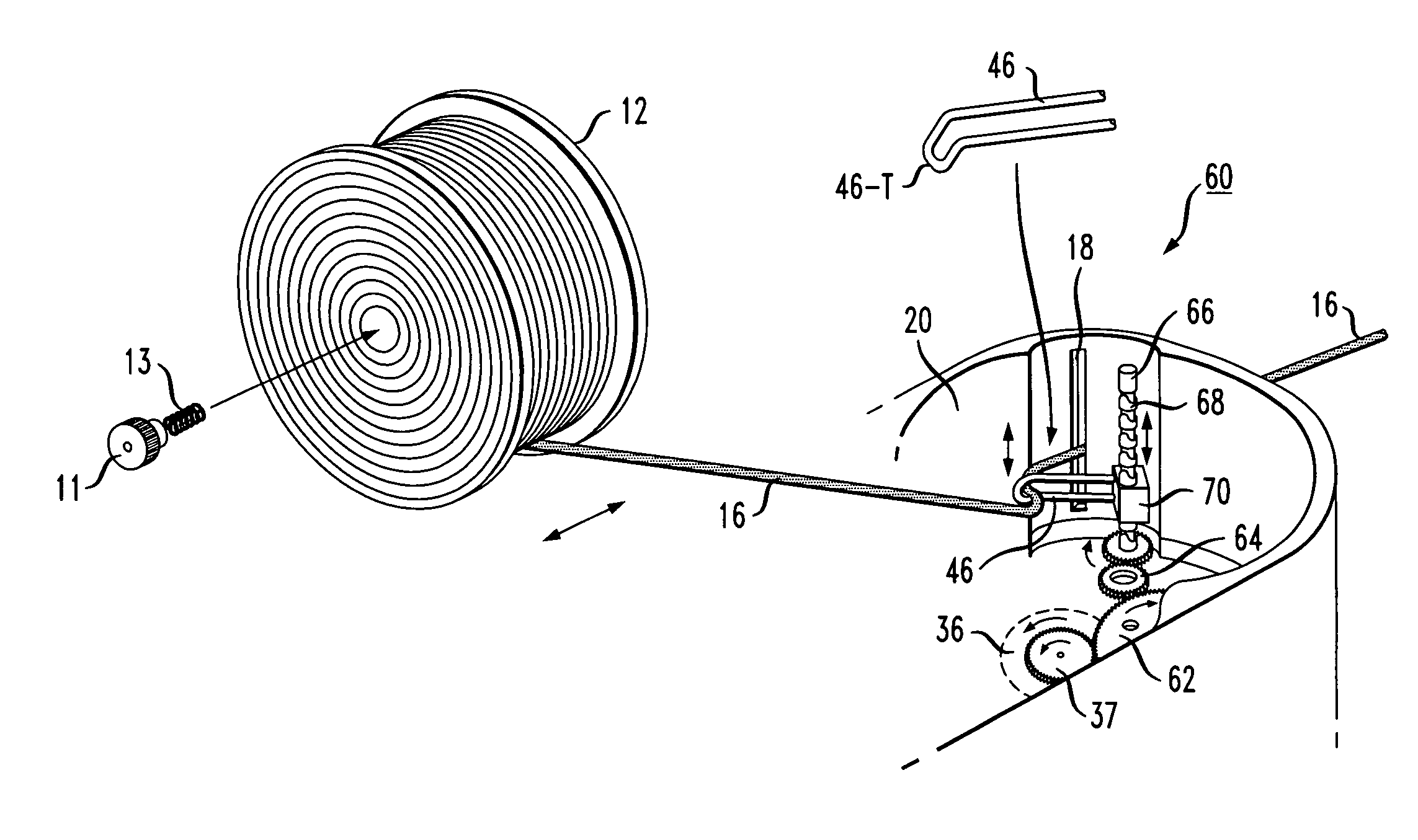
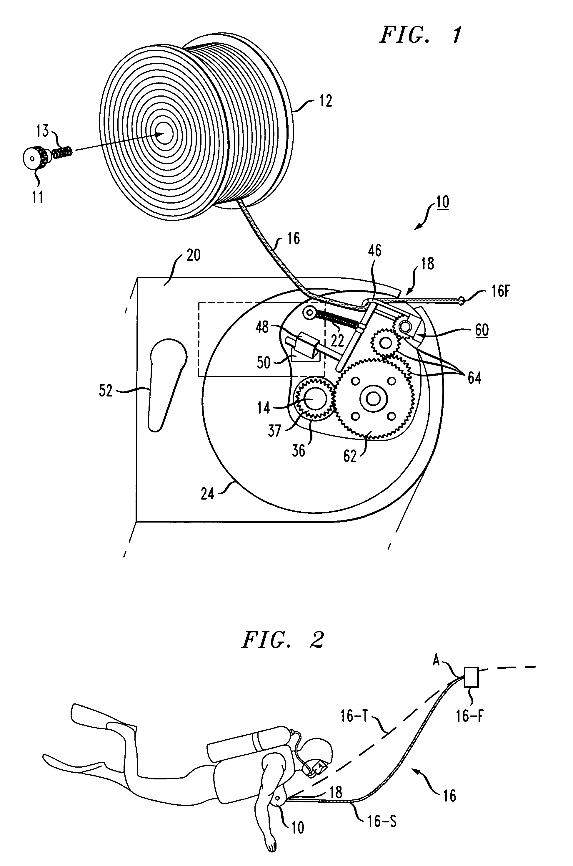
[0031]FIG. 1 illustrates, in a side (exploded) view, an exemplary motorized self-winding diver's reel 10 formed in accordance with the present invention. For illustrative purposes, take-up reel 12 has been removed from an associated axle 14 to clearly illustrate the various components utilized to form the self-winding portion of the inventive reel. As shown, a length of safety cord 16 is wound around take-up reel 12. When take-up reel 12 is in place over axle 14, the free end of cord 16 (denoted 16-F in FIGS. 1 and 2), is fed through an opening 18 in housing 20 of self-winding reel 10 and is thereafter attached to a diver's anchor line at a fixed point. Shown in association with take-up reel 12 is a tension knob 11 and a spring 13 that are inserted through the central aperture of take-up reel 12 so as to fit against axle 14. When take-up reel 12 is in place (as shown in FIG. 3), knob 11 can be turned to adjust the force that spring 13 applies against axle 14. This force will control...


PUM


Abstract

An automated reel for use by divers comprises a battery-operated motor in communication with a take-up reel through a gearing arrangement, where the activation / de-activation of the motor is controlled by a tension-sensing mechanism. In operation, when the mechanism senses that there is “slack” in the safety cord, the mechanism will turn “on” the motor, which will then cause the reel to rotate (via the gearing arrangement) to wind up the slack safety cord. Once tension is restored on the line, the mechanism will turn “off” the motor. A manual override switch may be included for situations where the diver desires to retain control of winding / unwinding of the safety cord. A line leveler arrangement may be used in conjunction with the reel so as to evenly distribute the safety cord across the extent of the reel.

Description

TECHNICAL FIELD[0001]The present invention relates to a diver's reel and, more particularly, to a diver's reel including a self-contained, battery-operated take-up reel that allows a sufficient length of safety cord to play out while a diver is moving away from his starting location and a tension-sensing device that automatically reels in a portion of the safety cord as soon as slack cord is created (as when the diver begins to return to his starting position).BACKGROUND OF THE INVENTION[0002]Poor visibility can greatly reduce the ability of a diver to return to a dive boat (or shore location) on his ascent. Safety guide lines, or cords, have been provided in the prior art on reels that are carried by the diver. In use, the diver follows the guide line to return to the exact origin of descent. These reels require attention and constant winding / unwinding by the diver during underwater activity to so as to maintain a direct line back to his ascent location, which is considered to be b...

Claims


Application Information

Patent Timeline
Patent Type & Authority Patents(United States)
IPC IPC(8): B65H27/00B63B22/18
CPCB63C11/02B63C11/26
Inventor KALETA, DENNIS ALFRED
Owner KALETA DENNIS ALFRED
Why Eureka
Try Eureka