
Outboard motor having a cowling
a technology of outboard motors and cowlings, which is applied in the field of outboard motors, can solve the problems of large amount of water flowing into the cowling, inability to control the flow rate of water into the engine chamber,
- Summary
- Abstract
- Description
- Claims
- Application Information
AI Technical Summary
Benefits of technology
Problems solved by technology
Method used
Image

Examples
Embodiment Construction
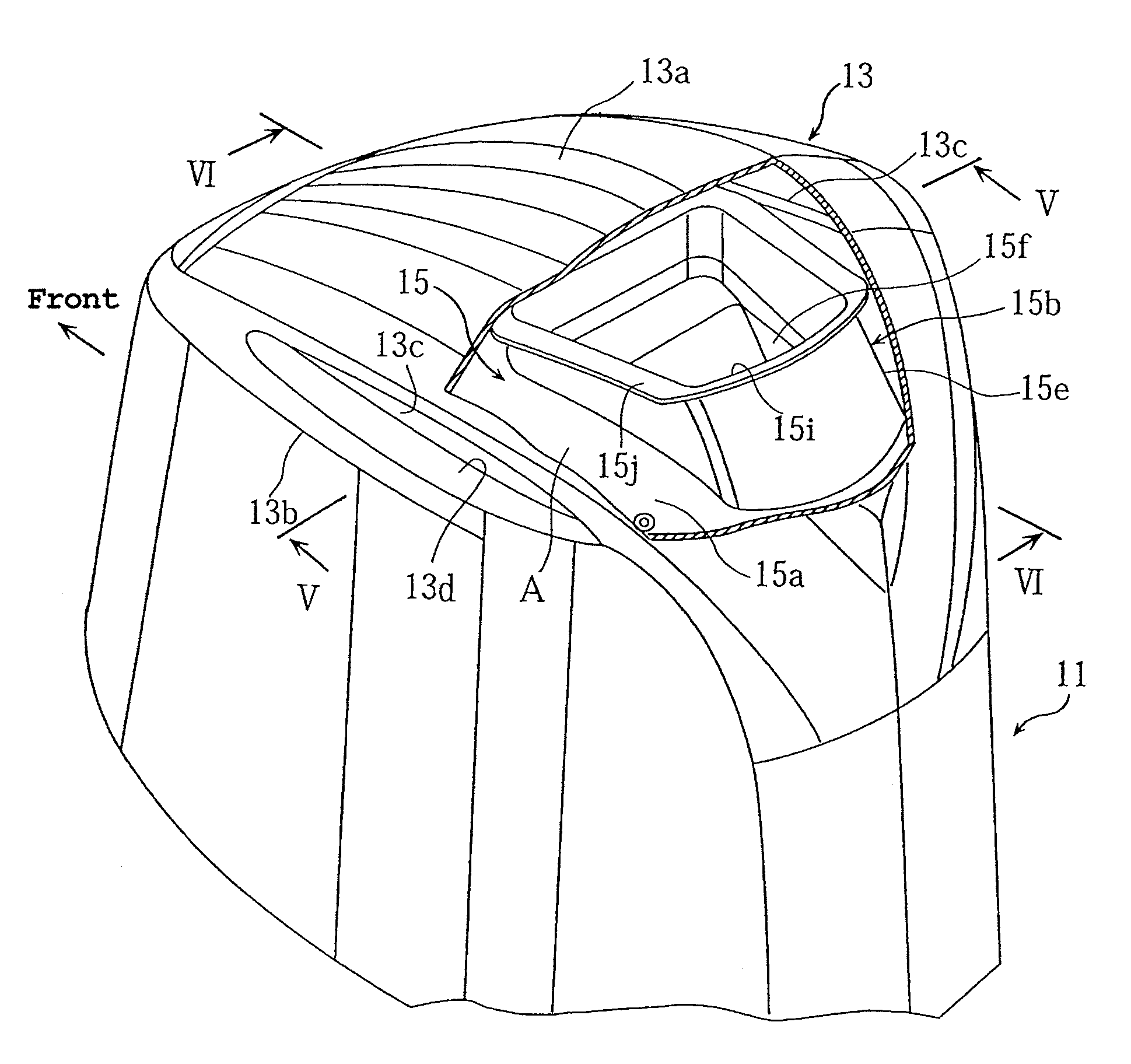
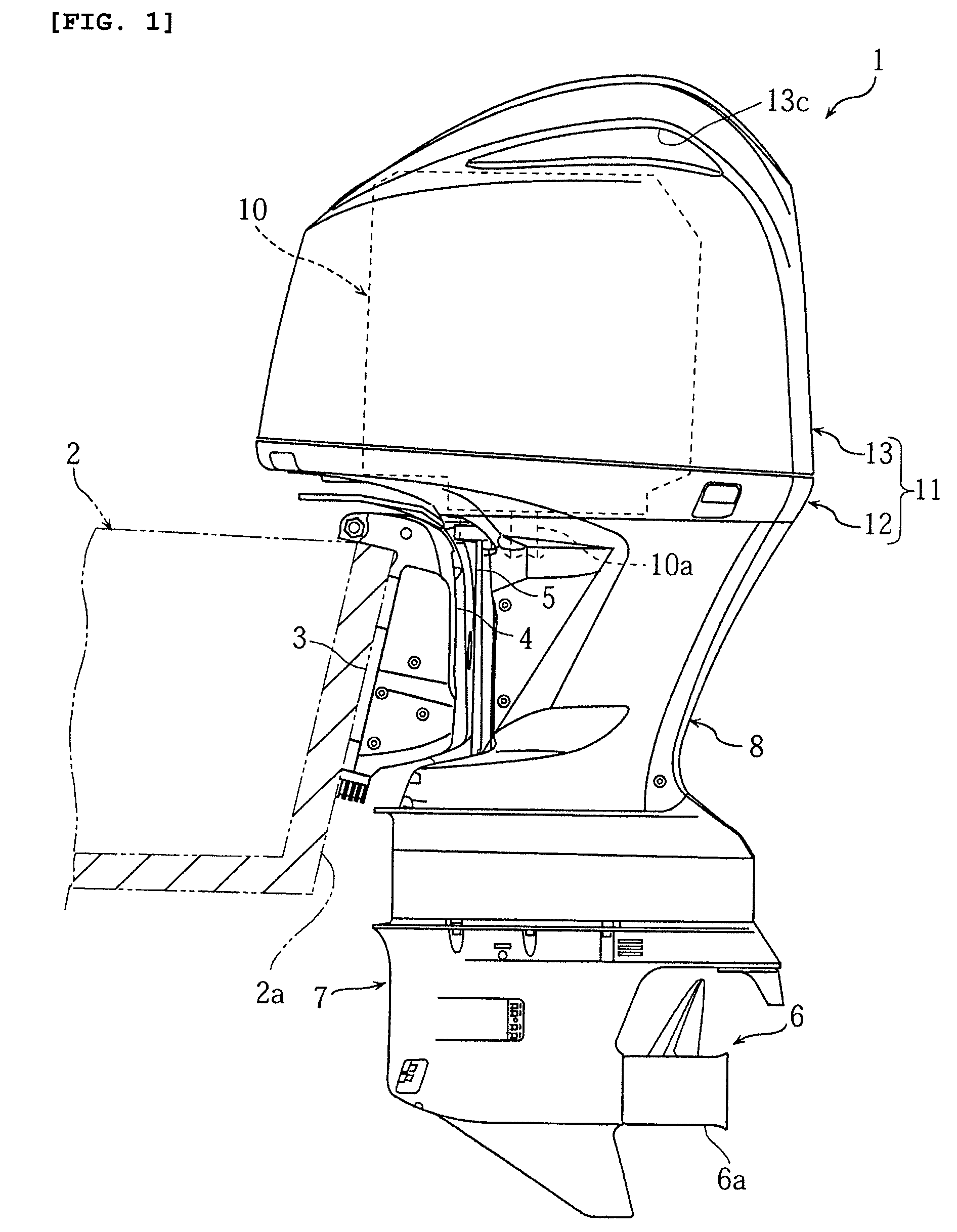
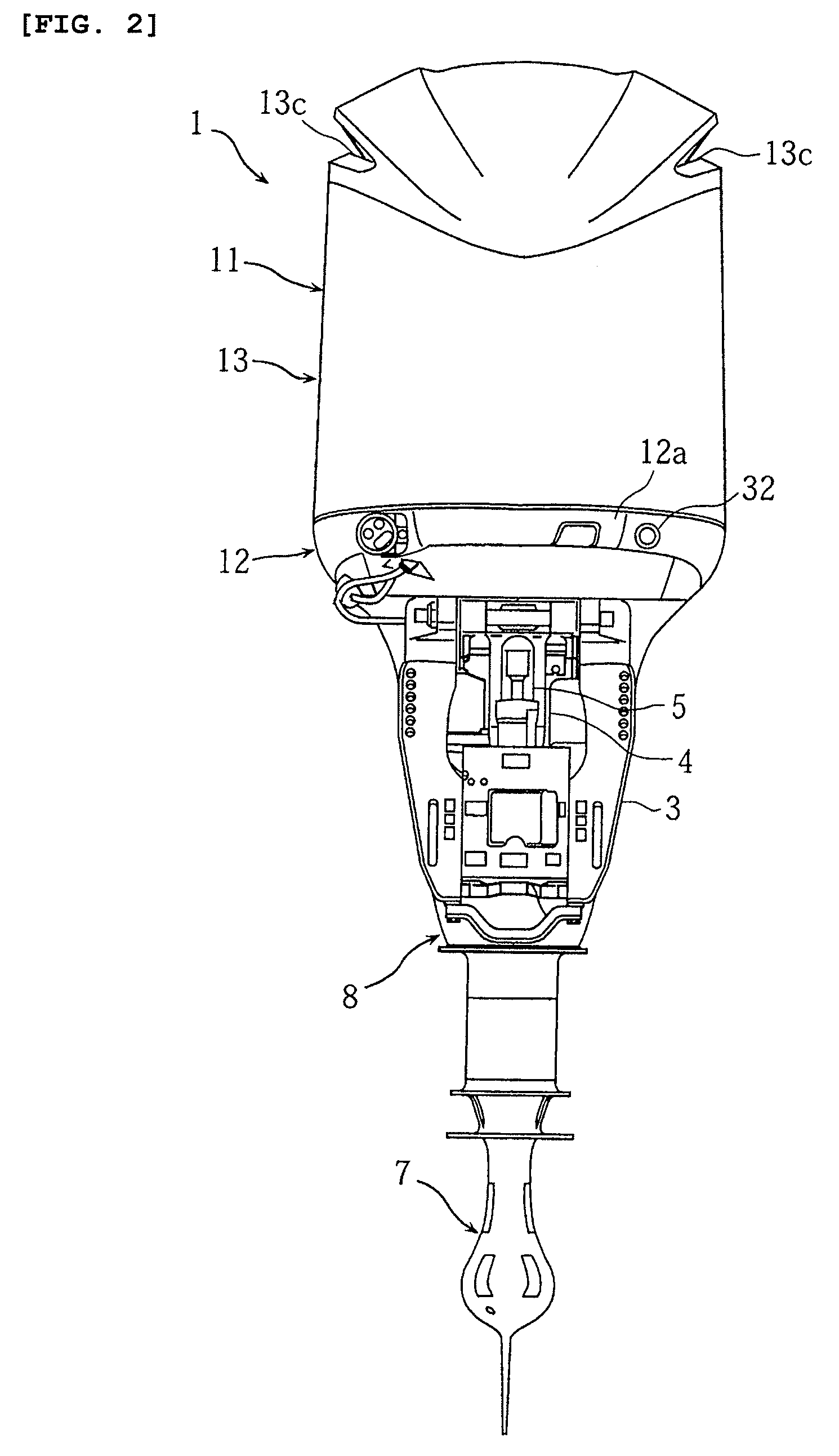
[0025]FIGS. 1 to 8 are intended to explain an outboard motor configured in accordance with some embodiments. FIG. 1 is a side view of an outboard motor; FIG. 2 is a front view of the outboard motor shown in FIG. 1; FIG. 3 is a sectional side view of a cowling surrounding an engine of the outboard motor shown in FIG. 1; FIG. 4 is a perspective view of the cowling shown in FIG. 3; FIG. 5 is a cross sectional view of the cowling shown in FIG. 4 (cross sectional view taken along the line V-V in FIG. 4); FIG. 6 is a sectional view of the cowling shown in FIG. 4 (sectional view taken along the line VI-VI in FIG. 4); FIG. 7 is a plan view of a molding; and FIG. 8 is a cross sectional view of the molding shown in FIG. 7 (cross sectional view taken along the line VIII-VIII in FIG. 6). The terms “right,”“left,”“front” and “rear” as used herein refer to right, left, front and rear as viewed from the side of the hull. It is to be understood that variations of the illustrated embodiments, such a...
PUM
 Abstract
Description
Claims
Application Information