Battery label with wireless battery charging circuit

Active Publication Date: 2008-11-25
IBM CORP
View PDF3 Cites 20 Cited by
  • Summary
  • Abstract
  • Description
  • Claims
  • Application Information

AI Technical Summary

Benefits of technology

[0006]The present invention provides an apparatus and method to allow batteries that use this invention to be inductively charged or re-charged while allowing the batteries to remain situated within their power receiving device. The present invention further eliminates the requirement for power transmitter to be electrically or mechanically connected to the power receiving device. The batteries of the present i

Problems solved by technology

However, one drawback of using rechargeable batteries is the constant requirement placed on the user to periodicall

Method used


Image

  • Battery label with wireless battery charging circuit
  • Battery label with wireless battery charging circuit
  • Battery label with wireless battery charging circuit

Examples


Embodiment Construction

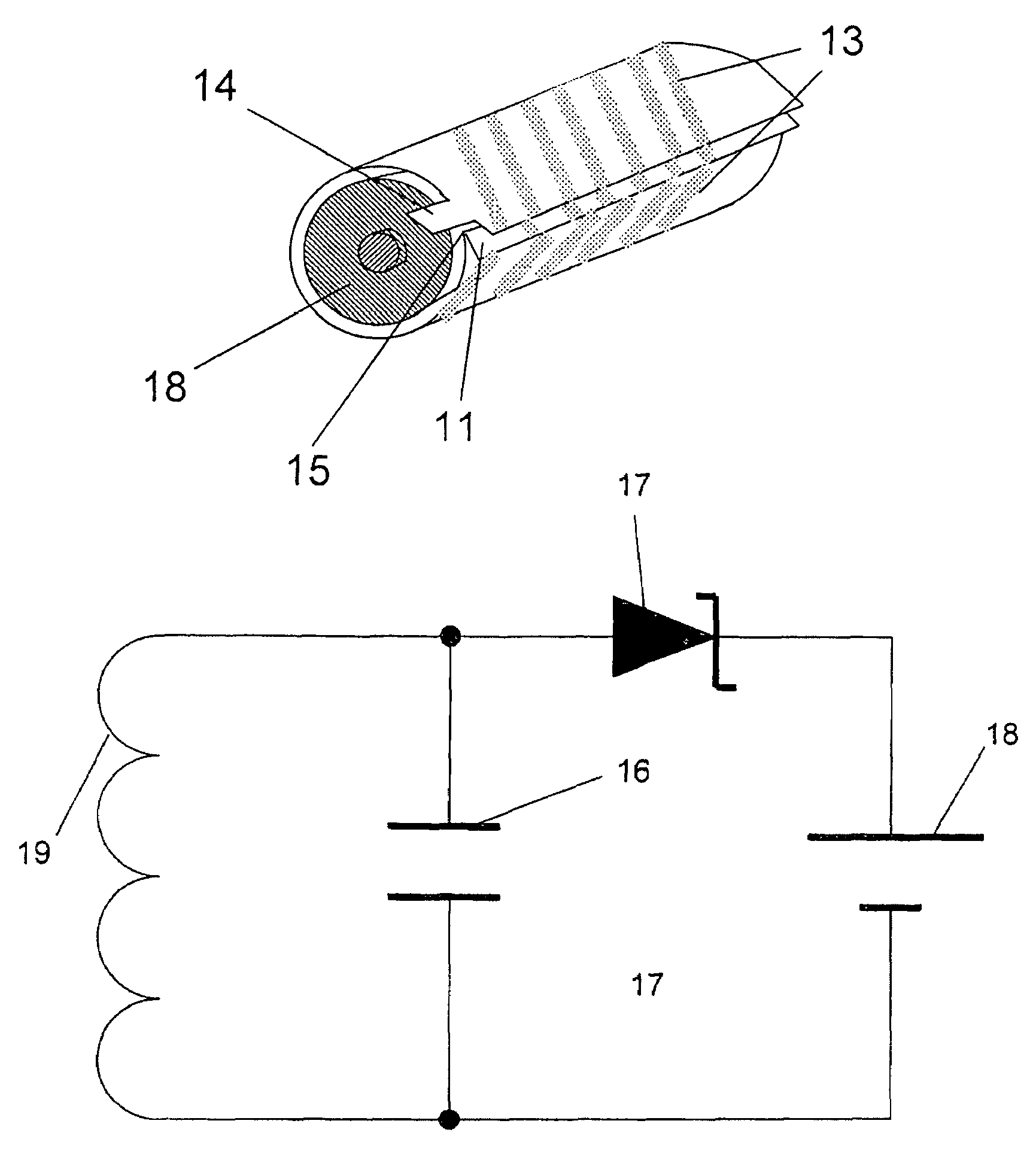
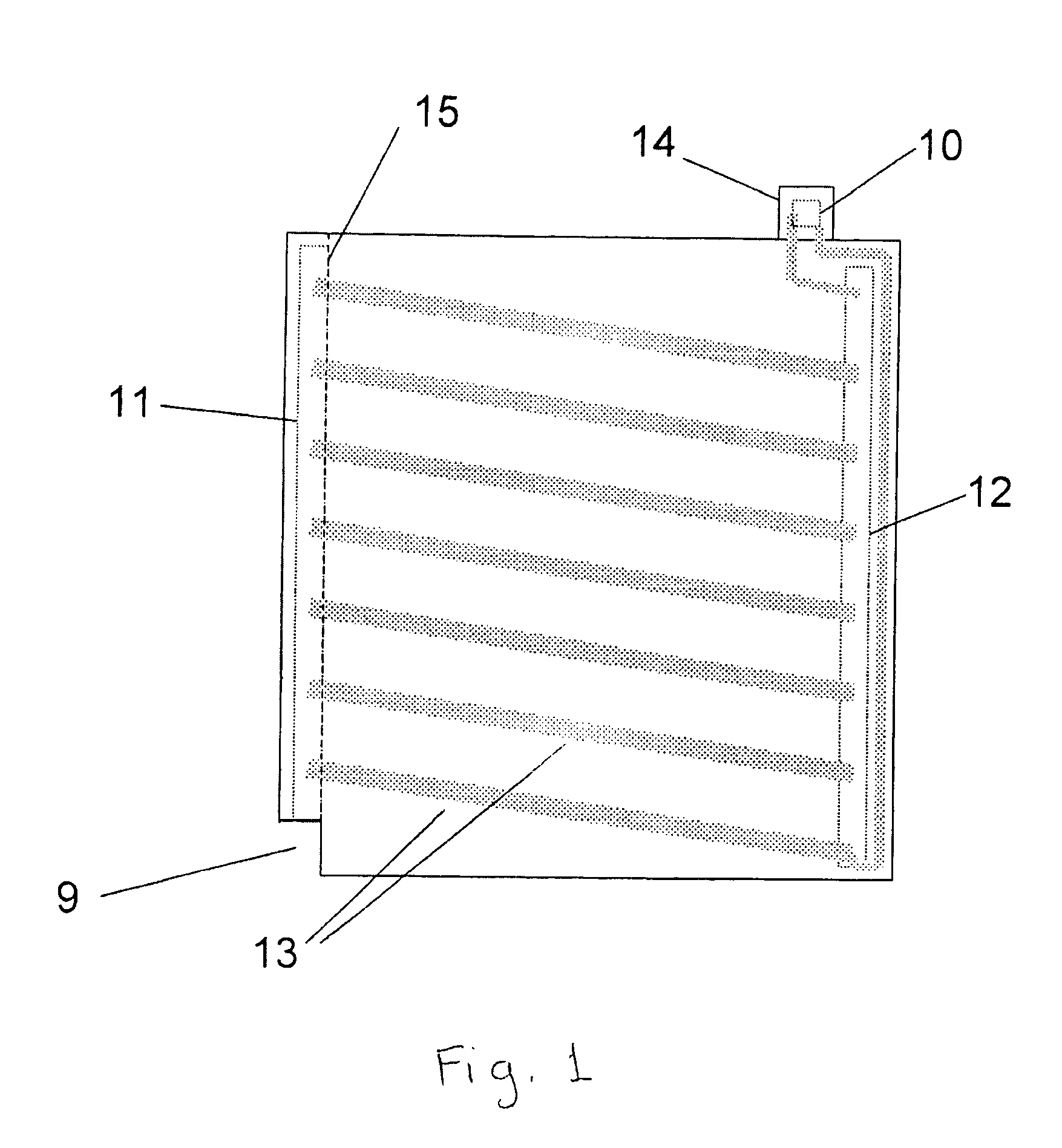
[0020]An embodiment of the present invention comprises a modified version of a standard AA (or other sized) battery. In this embodiment of the present invention, the reverse side of the label on the rechargeable cell is printed with a pattern of lines using conductive ink. Conductive inks are well-known. The pattern on the self adhesive label is shown at FIG. 1. Dimensions shown in FIG. 1 are for an “AA” sized battery which is typically 14 mm in diameter and 48 mm high. However, additional sized batteries may be used and the size of the adhesive label would be adjusted accordingly. The conductive ink pattern is overlaid with an insulating layer, then with the pressure sensitive adhesive that holds the label onto the cell once assembled. Three apertures 10, 11 and 12 are provided in the insulating layer and the adhesive layer.

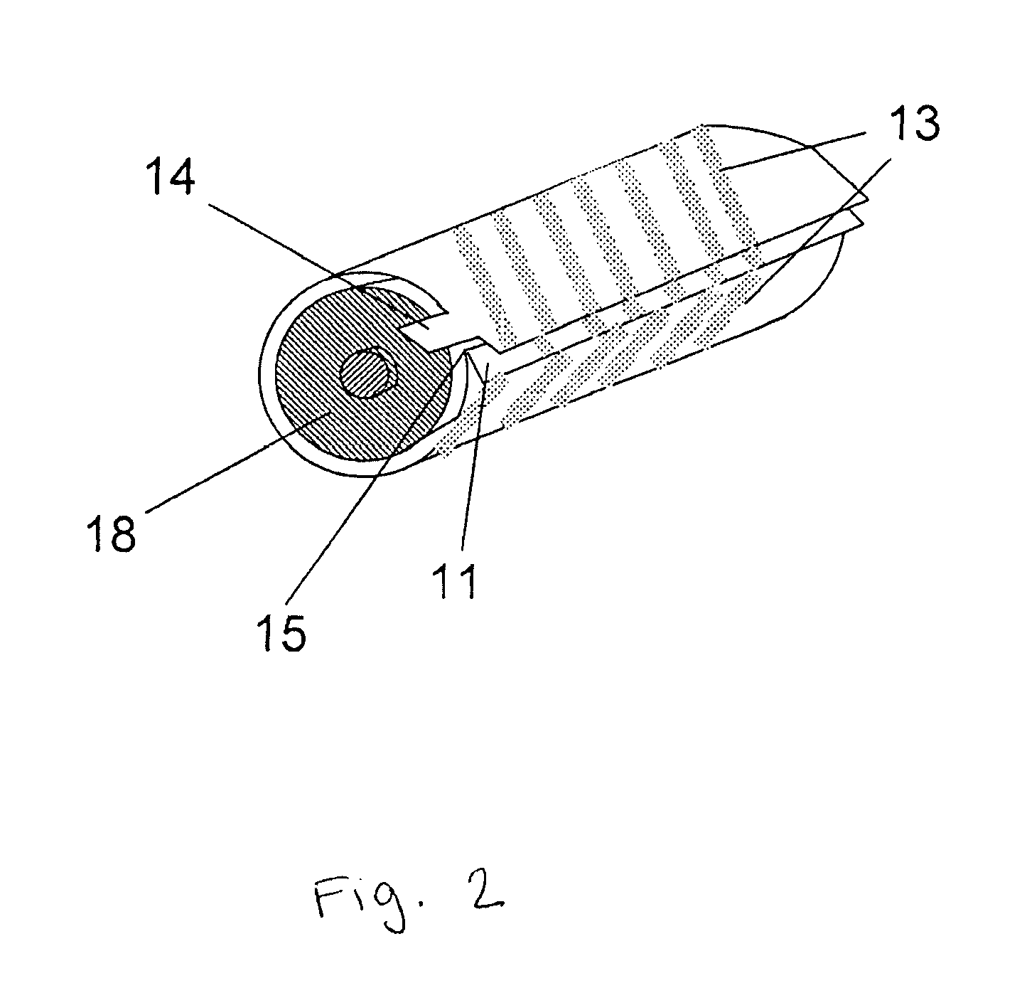
[0021]The label, as shown in FIGS. 1, 2, and 3 comprises four layers, and is made from a material that is well-known to one of ordinary skill in the art. The la...


PUM


Abstract

This invention relates to a cost effective and long-awaited apparatus and method for making a battery charging unit wherein the apparatus and method solution used induction to eliminate the requirement to constantly remove rechargeable batteries from their particular units in order to recharge them. This invention further relates to a cost-effective and long-awaited apparatus and method wherein the apparatus and method solution uses induction to eliminate the requirement to electrically or mechanically connect the charged device to a battery charging unit in order to recharge the battery.

Description

CROSS REFERENCE TO RELATED APPLICATIONS[0001]There are no cross-references related to this application.FIELD OF THE INVENTION [0002]The present invention relates to solid state technologies and more particularly to a charging circuit (i.e. power transmitter circuit) that uses induction to provide power transfer between a power transmitter such as a charging base and a power receiving device (i.e. eliminating the use of wires). Relevant potential applications for the present invention include any small portable hand-held device that uses standard sized batteries, but not limited to, calculators, cameras, mp3 players, CD players, GPS units, hand-held electronic instruments, hand-held medical instruments etc., or any device that requires batteries to be taken out for replacement or for recharging.BACKGROUND OF THE INVENTION[0003]Many hand-held devices use either non-rechargeable (primary) or rechargeable (secondary) cells for drawing power. Common cell sizes are AAA, AA, C, D, and the ...

Claims


Application Information

Patent Timeline
IPC IPC(8): H02J7/00H01Q11/12H04B1/16H04B1/38H01M50/119H01M50/126
CPCH02J7/025H02J50/10H02J50/20H02J2207/20H02J7/0042H01M10/425H01M10/46Y02E60/10H01M50/126H01M50/119H02J50/12
Inventor LEGG, STEPHEN PETER
Owner IBM CORP
Why Eureka
Try Eureka