Dynamic refractometer

a refractometer and dynamic technology, applied in the field of refractometers, can solve the problems of inherently static measurement of the refractive index using these devices, unable to measure the kinetics and inability to measure the real time or near-real time of the change of the refractive index during the photocuring process

Inactive Publication Date: 2008-11-25
CURLEY MICHAEL J +1
View PDF11 Cites 15 Cited by
  • Summary
  • Abstract
  • Description
  • Claims
  • Application Information

AI Technical Summary

Benefits of technology

[0015]The refractometer of the present invention further includes a curing means adapted to a cure polymeric mixture held in the spectroscopic cell. In preferred embodiments the polymeric mixture is a photocurable polymeric mixture and the curing means correspondingly includes a source of photonic radiation and a light transmission conduit adapted to channel the photonic radiation through the prismatic optical element and into the polymeric mixture within the spectroscopic cell. Thus, the prismatic optical element is used as an optical conduit for both the measuring light beam and the curing photonic radiation.
[0016]In one preferred embodiment the photocurable polymeric mixture is a photocurable polymer resin or adhesive. The spectroscopic cell includes container having an optical window that is optically coupled to a prism of cubic zirconium. The source of measurement light illuminating

Problems solved by technology

However, even if an optimal cure cycle is determined for a given chemical composition and application, uncontrolled or unobserved variations in the temperature, pressure, and/or intensity and duration of photonic irradiation used during cure still result in variations in the degree of polymerization of the polymer matrix.
A significant time delay between the change of the refractive index and the moment when the data is obtained makes real time or even near-real time measurement of the kinetics of the refractive index change du

Method used


Image

  • Dynamic refractometer
  • Dynamic refractometer
  • Dynamic refractometer

Examples


Embodiment Construction

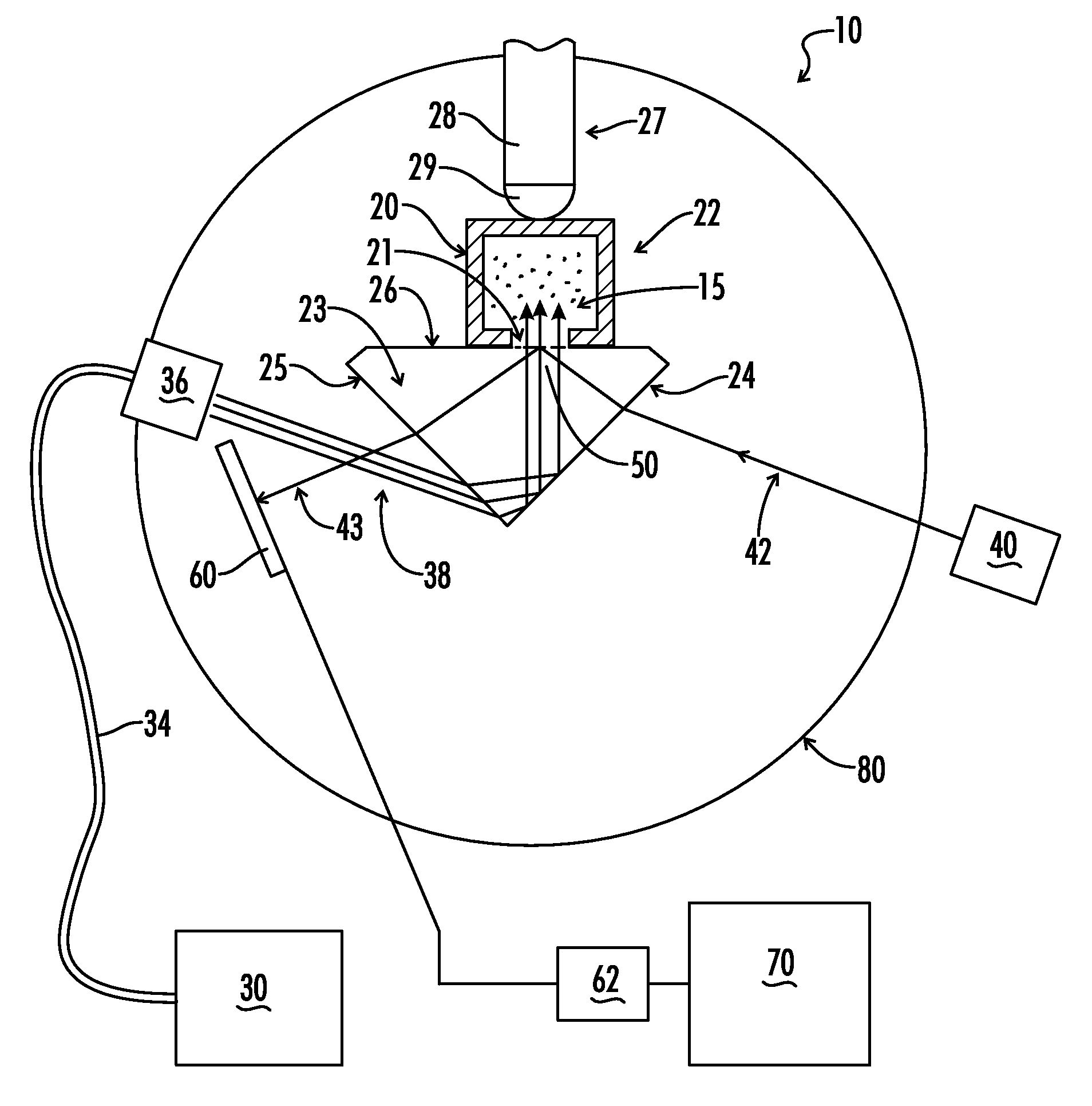
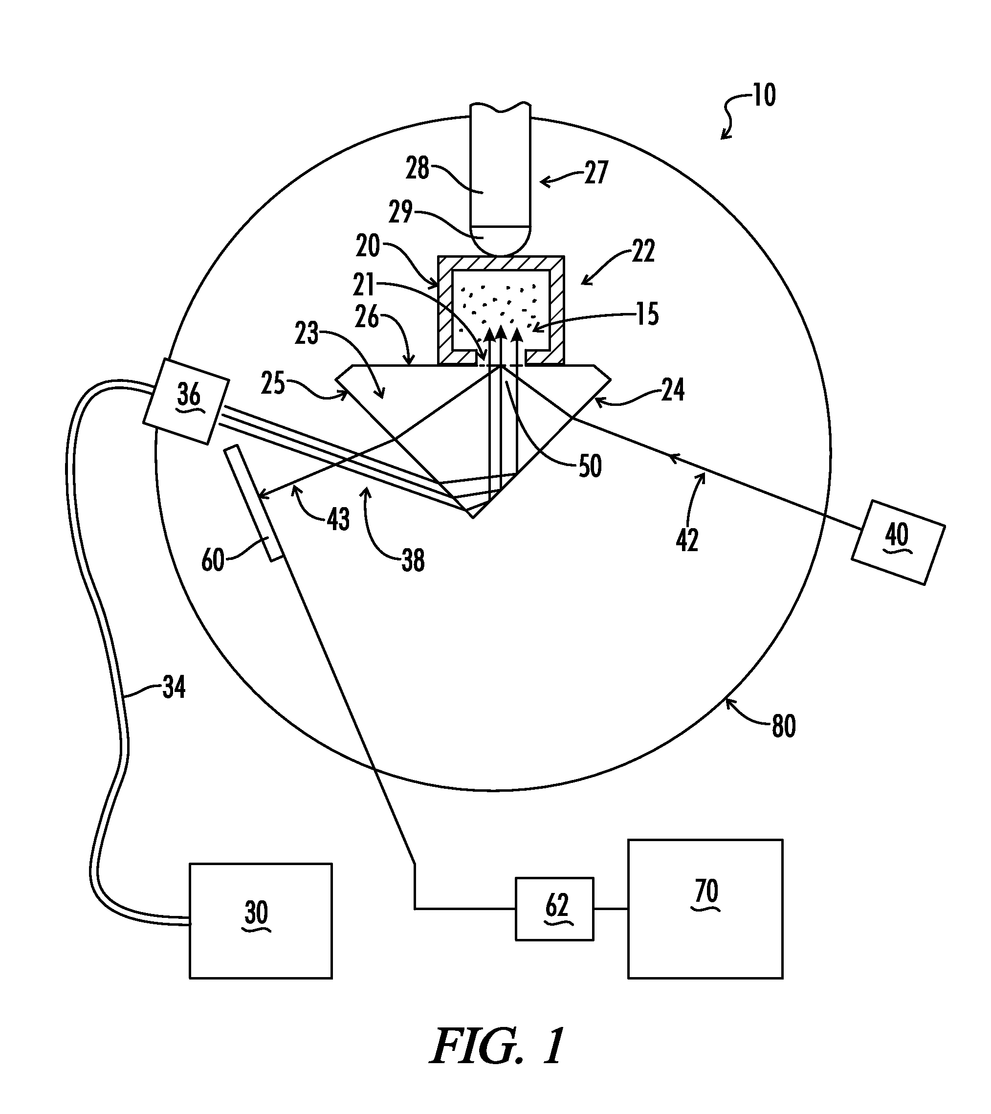
[0025]As shown in FIG. 1, the present invention is a novel refractometer 10 and includes a spectroscopic cell 22 for holding a polymeric mixture during the process of curing the polymeric mixture. The polymeric mixture exhibits a dynamic refractive index that changes generally continuously during the curing process from an initial refractive index of an uncured polymeric mixture to a final refractive index of a completely cured polymeric mixture. In one preferred embodiment the polymeric mixture is a photocurable polymer resin. In an alternate preferred embodiment the polymeric mixture is a photocurable adhesive. In the preferred embodiment shown in FIG. 1, a photocurable polymer resin 15 is held in a spectroscopic cell 22 used to splice optical fibers. The spectroscopic cell 22 includes rectangular container 20 having an optical window 21 disposed within one wall of the container 20. Optionally the spectroscopic cell 22 holds selected optical elements to be bonded or spliced by the...


PUM


Abstract

A refractometer computer controls the rotation of a rotary plate upon which are mounted a prism optically coupled via an optical window to a spectroscopic cell holding a resin exhibiting a dynamic refractive index during photocuring. The computer system positions the prism and spectroscopic cell relative to a visible light laser which illuminates the prism-resin interface at selected incidence angles. A photodetector mounted on the plate generates a signal to the computer proportional to intensity of an internally reflected light beam. A curing light is selectively transmitted through the prism and into the photocurable resin. The refractometer determines the intensity of the internally reflected beam a selected incidence angles and determines the effective refractive index curve of the resin at an uncured state and, optionally, at a completely cured state. Next, an amount of uncured resin and selected optical components to be joined by the resin is placed in the spectroscopic cell and irradiated with the UV light. The refractometer is fixed at a selected incidence angle and measures the intensity of an internally reflected light beam of light throughout the cure cycle. The refractometer determines the resin's refractive index of the polymeric mixture by means of extrapolation of a horizontal shift in the effective refractive index curve of the resin from an uncured state to a selected point in the cure cycle.

Description

STATEMENT REGARDING FEDERALLY SPONSORED RESEARCH OR DEVELOPMENT[0001]This invention was made with Government support under grant NAG8-1880 awarded by NASA. The Government has certain rights in the invention.BACKGROUND OF THE INVENTION[0002]The present invention relates generally to refractometers for measuring the refractive index of a translucent material during a physical or chemical process. More particularly, the invention relates to refractometers for measuring the refractive index of a transparent polymeric material during a curing process. Even more particularly, the invention relates to refractometers for continuously measuring the dynamic refractive index of a photocurable resin or adhesive mixture during the process of curing the mixture by means photonic irradiation.[0003]Growing demand for photocurable polymeric materials has necessitated the development of advanced process monitoring techniques to ensure high quality production of cured polymers at minimum cost. In part...

Claims


Application Information

Patent Timeline
IPC IPC(8): G01N21/41
CPCG01N21/43
Inventor CURLEY, MICHAEL J.SARKISOV, SERGEY S.
Owner CURLEY MICHAEL J
Why Eureka
Try Eureka