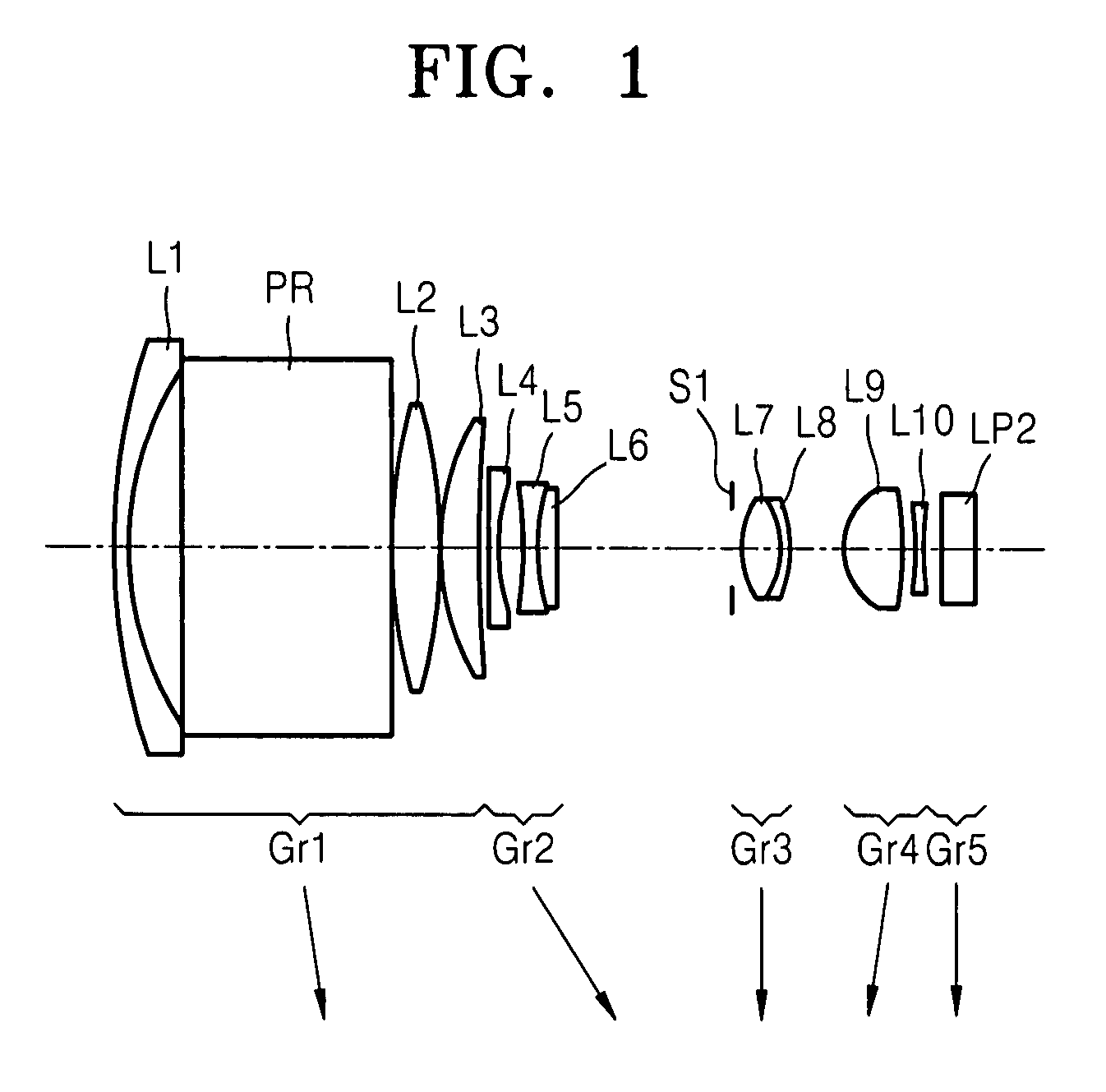
High magnification zoom lens system
a zoom lens and high magnification technology, applied in the field of slim, compact high, magnification zoom lens, can solve the problem of undesirable large size of this optical system for a slim, compact camera, etc., and achieve the effect of slim and compact, high magnification
- Summary
- Abstract
- Description
- Claims
- Application Information
AI Technical Summary
Benefits of technology
Problems solved by technology
Method used
Image
Examples
embodiment 1
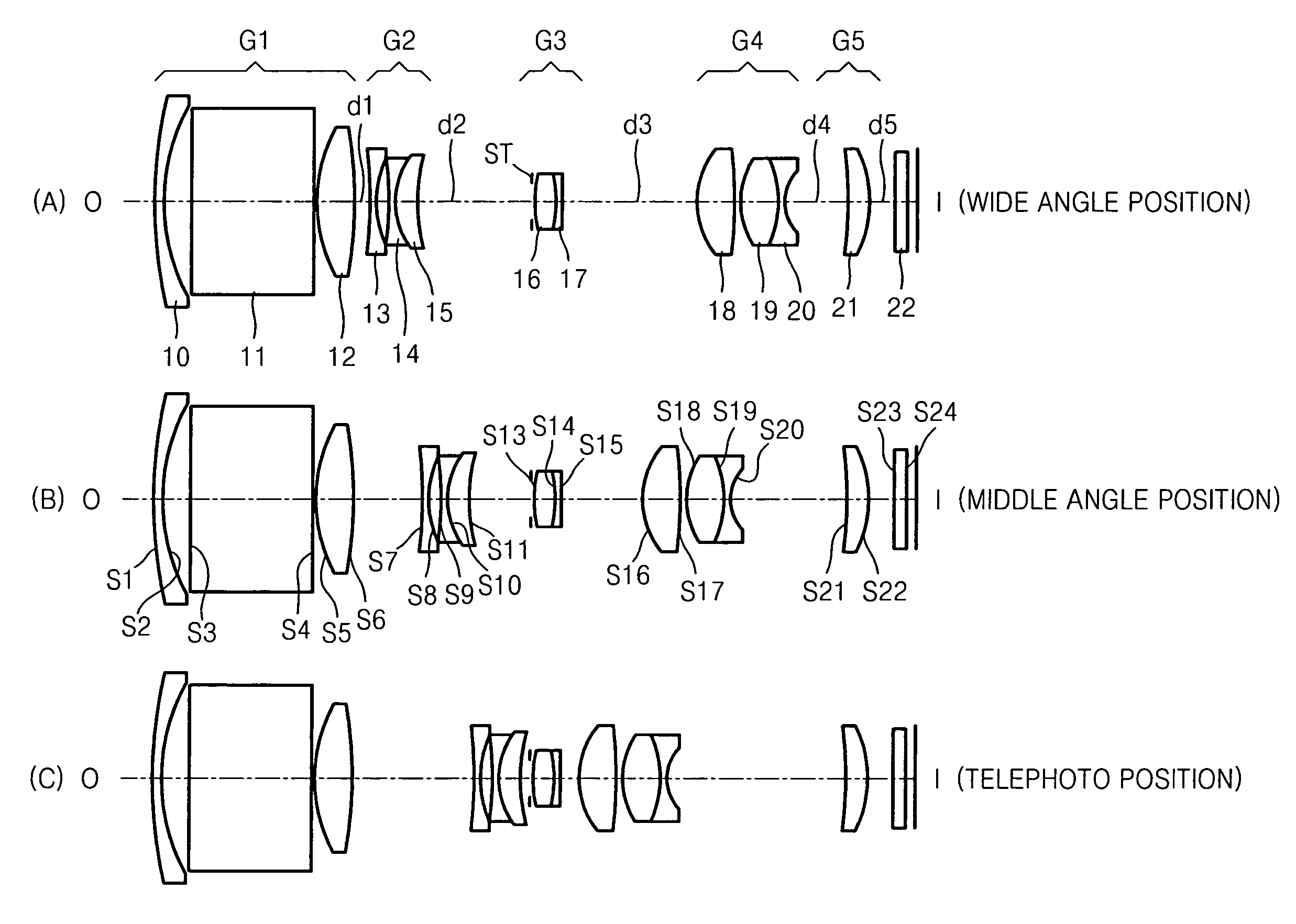
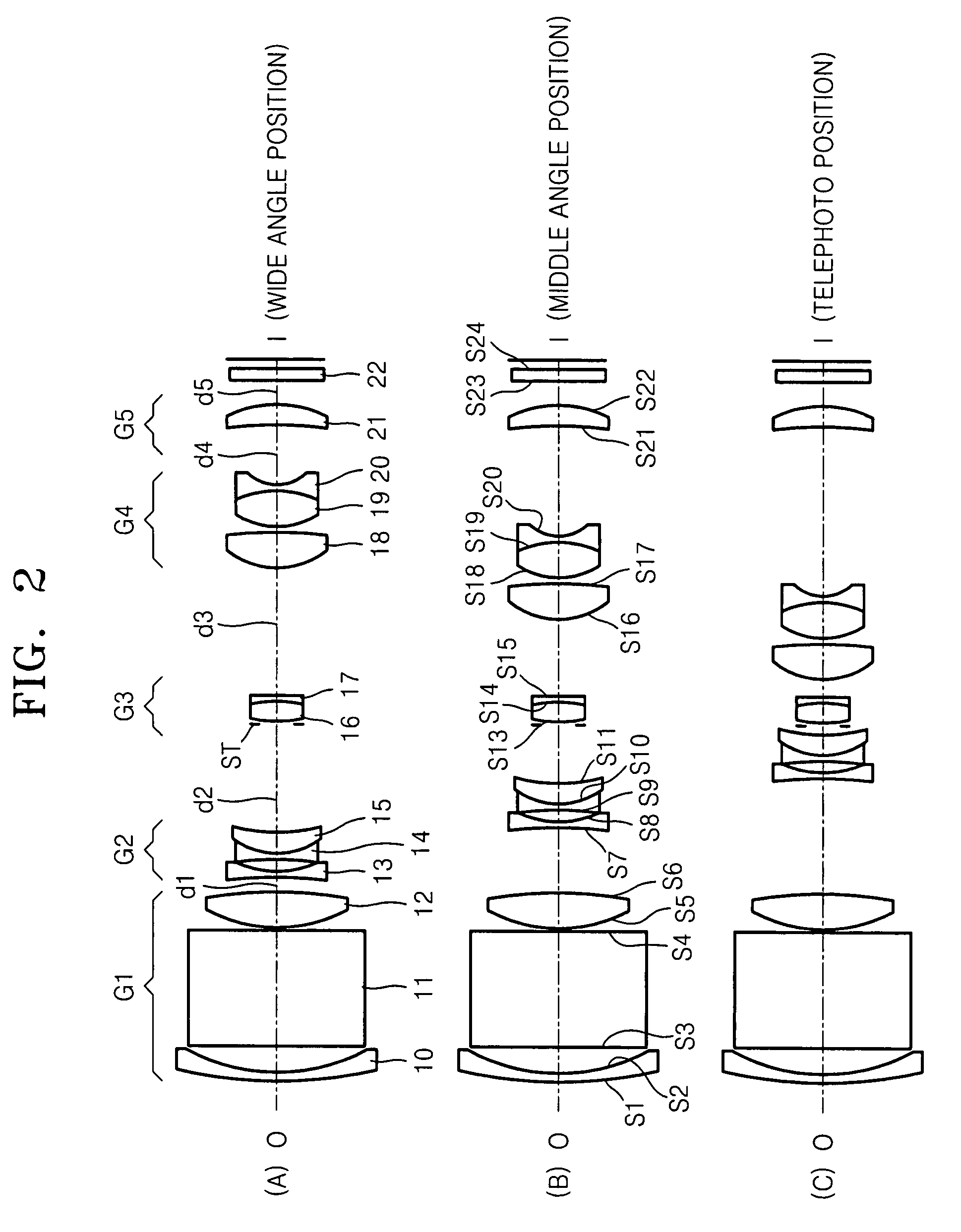
[0060]FIGS. 2A, 2B, and 2C show a zoom lens system according to an embodiment of the present invention which includes the first through fifth lens groups G1, G2, G3, G4, and G5.
[0061]
TABLE 1f: 6.00~13.51~32.97, Fno: 3.62~4.77~6.48, 2ω: 61.44~29.84~12.34Radius ofThickness orRefractive IndexAbbe NumberCurvature (r)Distance (d)(nd)(vd)S137.8290.651.9228620.88S214.5212.03S3infinity8.601.9228620.88S4infinity0.30S512.2092.681.6375860.45K: −0.694571A: −0.374792E−05 B: 0.369924E−07 C: −0.692696E−08D: 0.600702E−09S6−23.879d1K: −5.440827A: 0.127453E−04 B: −0.327023E−06 C: 0.161365E−07D: 0.200010E−09S7−58.2510.451.7550052.32S87.9780.87S9−35.6661.7342270.4553.45S105.6401.631.92285920.88S1114.377d2STInfinity0S1311.0961.521.70051436.23S14−7.3520.451.91164825.87S15−87.217d3S166.4272.851.5191376.59S17−16.418740.23K: −4.873103A: 0.471717E−03 B: 0.144794E−05 C:S185.7632.801.5387557.48S19−7.4940.451.8484536.00S203.952d4S21968.2221.861.5312055.70K: 10A: −0.290904E−04 B: −0.251500E−04 C: 0.228308E−05S22...
embodiment 2
[0065]FIGS. 4A, 4B, and 4C show a zoom lens system according to another embodiment of the present invention. The first lens group G1 includes a first lens element 40, a reflection member 41, and a second lens element 42, the second lens group G2 includes a third lens element 43 and first combined lens elements 44 and 45, the third lens group G3 includes an aperture ST and second combined lens elements 46 and 47, the fourth lens group G4 includes fourth, fifth, and sixth lens elements 48, 49, and 50, and the fifth lens group G5 includes a seventh lens element 51. The zoom lens system further includes a cover glass 52.
[0066]
TABLE 3f: 6.00~13.27~28.50, Fno: 3.65~4.54~5.39, 2ω: 62.57~31.10~14.29Radius ofThickness orRefractive IndexAbbe NumberSurfaceCurvature (r)Distance (d)(nd)(vd)S140.2230.651.8466623.78S213.9361.841S3Infinity8.61.83437.34S4Infinity0.3S512.0282.7941.5955763.76K: −0.644871A: −0.698588E−06 B: 0.528857E−07 C: −0.108341E−07S6−19.366d1K: −5.282013A: 0.109152E−04 B: −0.40109...
embodiment 3
[0070]FIGS. 6A, 6B, and 6C show a zoom lens system according to another embodiment of the present invention. The first lens group G1 includes a first lens element 60, a reflection member 61, and a second lens element 62, the second lens group G2 includes a third lens element 63 and first combined lens elements 64 and 65, the third lens group G3 includes an aperture ST and second combined lens elements 66 and 67, the fourth lens group G4 includes fourth, fifth, and sixth lens elements 68, 69, and 70, and the fifth lens group G5 includes a seventh lens element 71. The zoom lens system further includes a cover glass 72.
[0071]
TABLE 5f: 6.31~12.66~29.59, Fno: 3.72~4.25~4.91, 2ω: 62.05~31.66~13.63AbbeRadius ofThickness orRefractive IndexNumberSurfaceCurvature (r)Distance (d)(nd)(vd)S176.4830.651.8466623.78S218.0721.72S3infinity8.601.8340037.35S4infinity0.30S512.0953.731.5891361.25K: −0.762734A: 0.000000E+00 B: 0.000000E+00 C: 0.000000E+00D: 0.000000E+00S6−20.043d1K: −5.032511A: 0.205073E−...
PUM
 Abstract
Description
Claims
Application Information
 - R&D
- Intellectual Property
- Life Sciences
- Materials
- Tech Scout
- Unparalleled Data Quality
- Higher Quality Content
- 60% Fewer Hallucinations
Browse by: Latest US Patents, China's latest patents, Technical Efficacy Thesaurus, Application Domain, Technology Topic, Popular Technical Reports.
© 2025 PatSnap. All rights reserved.Legal|Privacy policy|Modern Slavery Act Transparency Statement|Sitemap|About US| Contact US: help@patsnap.com


