Mixer circuit for direct conversion transceiver with improved IP2

a technology of mixer circuit and direct conversion transceiver, which is applied in vibration massage, modulation, transportation and packaging, etc., can solve the problems of i-q mismatch, dc component of mixer, error in reception/transmission, etc., and achieve the effect of improving ip2 characteristics and improving ip2 characteristics

Inactive Publication Date: 2008-11-25
SAMSUNG ELECTRONICS CO LTD
View PDF15 Cites 44 Cited by
  • Summary
  • Abstract
  • Description
  • Claims
  • Application Information

AI Technical Summary

Benefits of technology

[0033]The signals outputted from two the switches controlled by four phase-shifted local oscillation signals remove I-Q mismatch and a DC component, and improve IP2 characteristics. Embodiments of the invention provide a single-balanced mixer circuit having improved IP2 characteristics by modifying a mixer structure and a LO signal input terminal.

Problems solved by technology

However, the direct conversion may have problems such as self-mixing, I-Q mismatch, and a DC component from the mixer.
In case where two applied and separated signals have a different magnitude from each other or have a phase difference other than 90° between two signals, there is a high possibility that an error in a reception / transmission will occur.
The IMD raises a problem when two frequencies pass through a single non-liner system and components relating to the sum and the difference of harmonics of the two frequencies are detected at the output side and can interfere with modulation and demodulation.
This method of improving the IP2 characteristic has the limitation that it is necessary but difficult to finely adjust the load impedance 111.
However, in a case where the frequency of the RF signal is relatively high, this method has the disadvantage that an I-Q mismatch is generated and the IP2 characteristic is degraded by even a minor change of the load impedance 111.

Method used


Image

  • Mixer circuit for direct conversion transceiver with improved IP2
  • Mixer circuit for direct conversion transceiver with improved IP2
  • Mixer circuit for direct conversion transceiver with improved IP2

Examples


Embodiment Construction

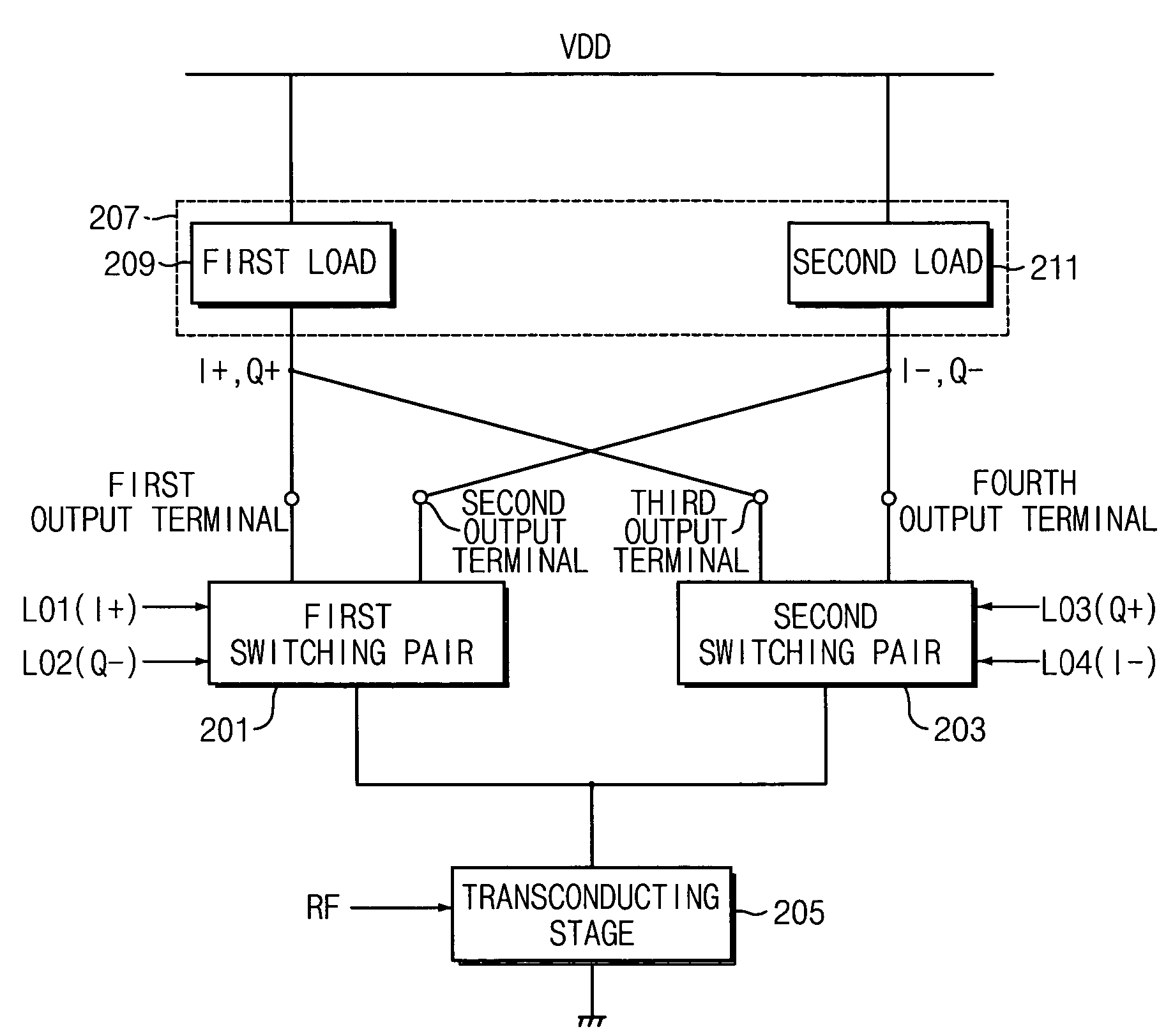
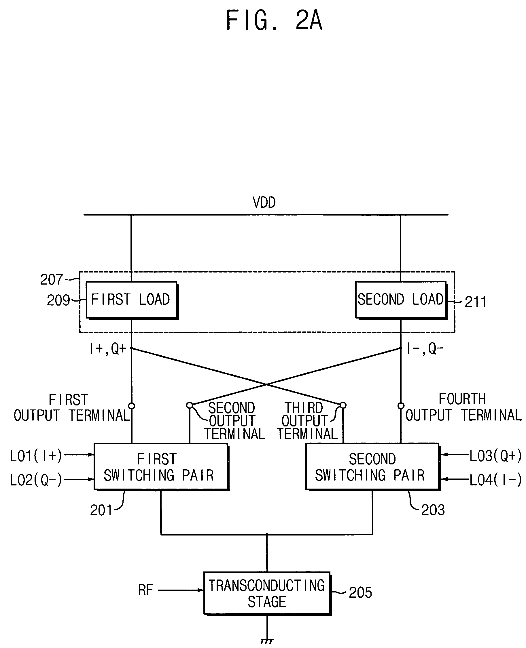
[0047]FIGS. 2A2B, and 2C are block and circuit diagrams illustrating a single-balanced mixer according to an exemplary embodiment of the present invention.

[0048]While a conventional single-balanced mixer includes a switching pair and one transconducting stage (having one transistor), a mixer according to the present embodiment includes two switching pairs and one transconducting stage (having one transistor). Thus, the mixer of the exemplary embodiment of the present invention may not be a “single-balanced” mixer in the strictest sense. However, for convenience, the mixer of the first exemplary embodiment will be hereinafter called a single-balanced mixer.

[0049]The single-balanced mixer of FIG. 2A, includes a first switching pair 201, a second switching pair 203, a transconducting stage 205, and a load impedance circuit 207.

[0050]The first switching pair 201 receives a first local oscillator signal LO1 and a second local oscillator signal LO2. In a case where the first local oscilla...


PUM


Abstract

A mixer for direct conversion transmitters and receivers using four phase-shifted local oscillation signals that are orthogonal each other to control a plurality of switches for outputting signals that are orthogonal each other. Two output signals that are orthogonal to each other do not mutually interfere and have a predetermined small signal gain. Further, a mixer may include four or eight switches controlled by four phase-shifted local oscillation signals that are orthogonal each other for outputting signals that are orthogonal to each other on an I-Q plot. The signals outputted from the switches controlled by four phase-shifted local oscillation signals remove I-Q mismatch and a DC component, and improve IP2 characteristics.

Description

CLAIM FOR PRIORITY[0001]This application claims priority under 35 USC § 119 to Korean Patent Application No. 2004-5995 filed on Jan. 30, 2004, the contents of which are herein incorporated by reference in its entirety.BACKGROUND OF THE INVENTION[0002]1. Field of the Invention[0003]The present invention relates to a radio frequency communication system, and more particularly to a mixer circuit used in a direct conversion transmitter and receiver.[0004]2. Description of the Related Art[0005]The baseband signal in a radio frequency (RF) wireless communication system is converted into a (higher) carrier frequency for transmission and at the receiver the carrier frequency is converted back into a baseband signal. For transmission, the baseband signal is modulated to the carrier frequency and outputted to an antenna. A frequency conversion in the transmission is called an “up-conversion. For reception, the carrier signal is detected by an antenna and is demodulated to a baseband for its o...

Claims


Application Information

Patent Timeline
Patent Type & Authority Patents(United States)
IPC IPC(8): H04B1/26H04B1/28H04B1/30H03C3/40H03D7/14
CPCH03D7/1441H03D7/165H03D7/1433H03D7/1458H03C3/403H03D2200/0019B60R16/037A61H23/02
Inventor KIM, YOUNG-JIN
Owner SAMSUNG ELECTRONICS CO LTD
Why Eureka
Try Eureka