
Mixer bias circuit

a bias circuit and mixer technology, applied in the field of mixer bias circuits, can solve the problems of affecting the sensitivity of the rf rxfe, the ip2 degradation of the calibrated mixer, and the imr performance of the dc offset and image rejection ratio (imr), so as to improve the ip2

Active Publication Date: 2020-07-02
REALTEK SEMICON CORP
View PDF0 Cites 0 Cited by
  • Summary
  • Abstract
  • Description
  • Claims
  • Application Information

AI Technical Summary

Benefits of technology

The mixer bias circuit described in this patent provides multiple bias voltages that adjust the performance of RF receivers. It uses a special technique to keep track of the common-mode voltage and compensates for any imbalance or mismatch effects in the circuit. This results in improved performance at the RF receiver front-end.

Problems solved by technology

Generally, the performance of a mixer suffers from various effects such as imbalance, mismatch, temperature, and fabrication process, subsequently influencing the IP2, DC offset, and image rejection ratio (IMR) performances of an RF RXFE.
However, those proposed techniques are possibly under the influence of a common-mode voltage variation induced by a TIA, resulting in an IP2 degradation of the calibrated mixer.
However, the nonlinear components such as the third order intermodulation distortion (hereinafter referred to as IMD3) and IMD2 would degrade the sensitivity of the RF RXFE.
Additionally, the mismatch and asymmetrical effects existing in the electronic devices of a mixer would enlarge the IMD2.
However, the proposed IP2 calibration techniques still suffer from the common-mode voltage variation from a TIA, leading to a degradation of the optimized IP2.

Method used


Image

  • Mixer bias circuit
  • Mixer bias circuit
  • Mixer bias circuit

Examples


Embodiment Construction

[0022]The following description is written by referring to terms of this technical field. If any term is defined in this specification, such term should be explained accordingly. In addition, the connection between objects or events in the below-described embodiments can be direct or indirect provided that these embodiments are practicable under such connection. Said “indirect” means that an intermediate object or a physical space exists between the objects, or an intermediate event or a time interval exists between the events.

[0023]The disclosure herein includes a mixer bias circuit. On account of that some or all elements of the mixer bias circuit could be known, the detail of such elements is omitted provided that such detail has little to do with the features of this disclosure and this omission nowhere dissatisfies the specification and enablement requirements. A person having ordinary skill in the art can choose components equivalent to those described in this specification to...


PUM


Abstract

The present invention discloses a mixer bias circuit including a first reference voltage generation circuit, an amplifier, a first transistor array, a first switch array, a second reference voltage generation circuit, a second transistor array, a second switch array, a first resistive component, and a second resistive component. The mixer bias circuit provides multiple bias voltages by dynamically tracking the common mode voltage of a trans-impedance amplifier (TIA) and compensates for imbalance and mismatch effects by asymmetrically trimming the bias voltages to improve the second-order intercept point of a radio frequency (RF) receiver front-end (RXFE).

Description

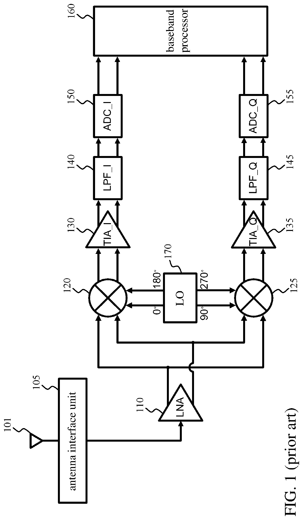
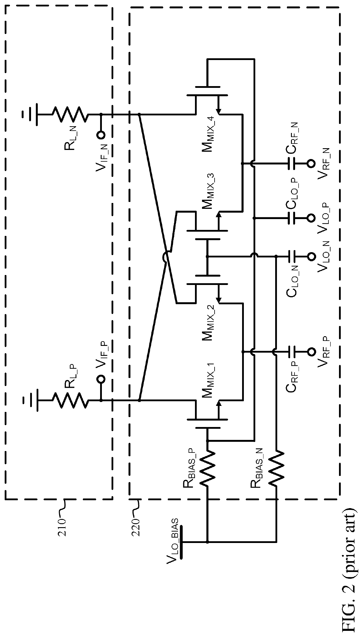
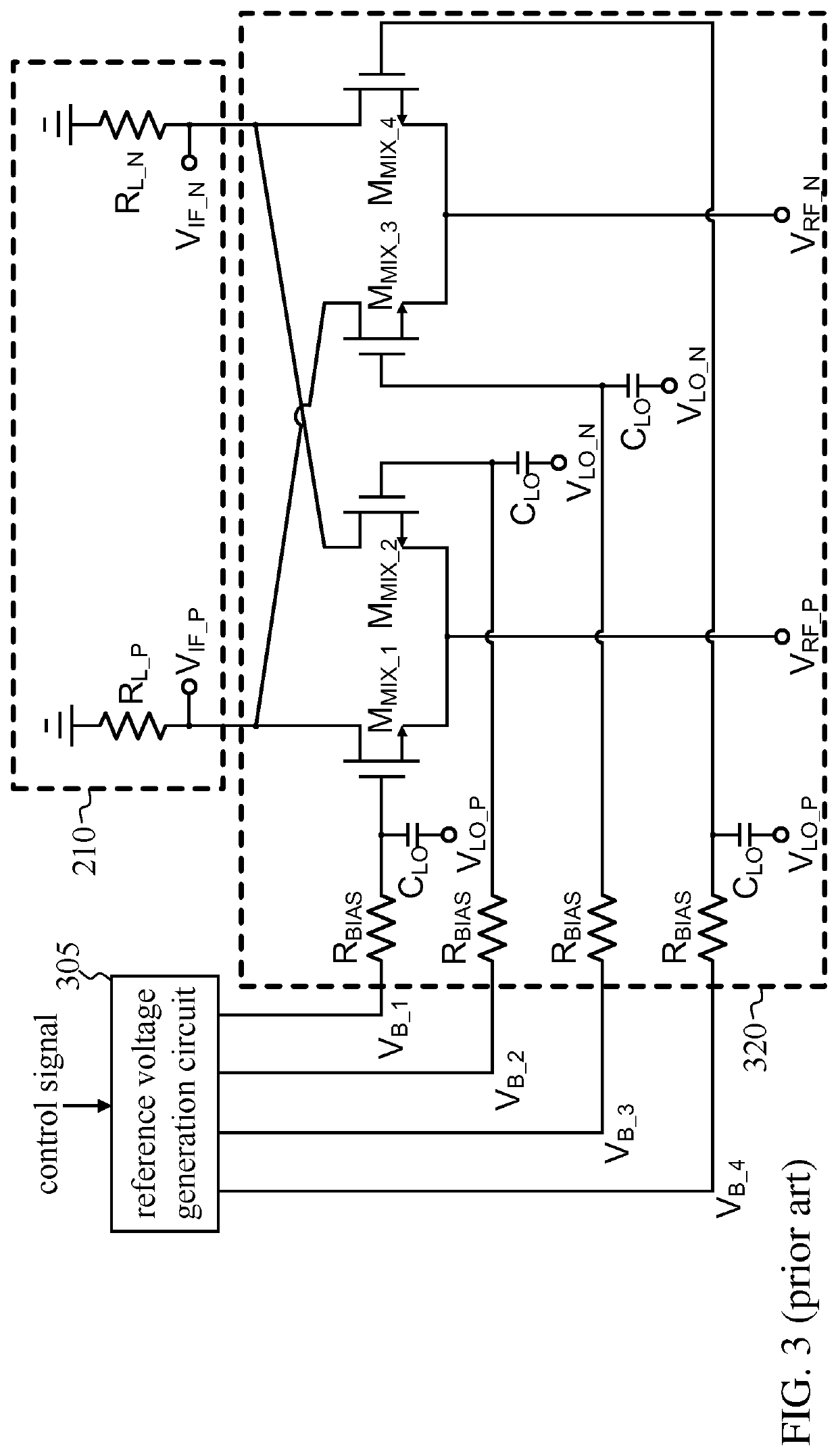
BACKGROUND OF THE INVENTION1. Field of the Invention[0001]The present invention generally relates to a mixer bias circuit, and, more particularly, to a mixer bias circuit having a second-order intercept point (hereinafter referred to as IP2) calibration function.2. Description of Related Art[0002]Despite its wide use in a radio frequency (RF) transceiver due to its high integration and low power consumption, a mixer comprising metal-oxide-semiconductor field-effect transistors (MOSFETs) confronts some design challenges such as low output direct current (DC) offset and high linearity characterized by the IP2 and the third-order intercept point (hereinafter referred to as IP3). A conventional receiver can be implemented with a direct-conversion architecture, as shown in FIG. 1. The antenna 101 receives a downlink (DL) RF signal, and outputs the received DL RF signal to a low-noise amplifier (LNA) 110 via an antenna interface unit 105. The antenna interface unit 105 may be consisted of...

Claims


Application Information

Patent Timeline
Patent Type & Authority Applications(United States)
IPC IPC(8): H03D7/12H04B1/16
CPCH03F3/45H03D2200/0088H03D7/125H04B1/16H03D7/1425H03D7/1466H03D7/1458H03D7/1441H03D2200/0043H03D7/165H03F3/45475H03F3/195H03F2200/294H03F2200/451H03F3/347H04B1/30
Inventor CHAN, KA-UNYEH, RONG-FUWU, CHAO-HUANG
Owner REALTEK SEMICON CORP
Learn More