Machine status interlock for reversing fan control

a technology of status interlock and fan, which is applied in the direction of motor/generator/converter stopper, dynamo-electric converter control, ventilation system, etc., can solve the problems of affecting the cooling ability of the associated radiator, affecting the effectiveness of the air circulation system, and affecting the cooling effect of the air intake screen

Inactive Publication Date: 2008-12-02
CATERPILLAR INC
View PDF6 Cites 12 Cited by
  • Summary
  • Abstract
  • Description
  • Claims
  • Application Information

AI Technical Summary

Problems solved by technology

As a result, materials such as dirt, insects, trash, leaves and the like can become lodged on the air intake screen.
As material accumulates on the air intake screen, the effectiveness of the air circulation system, and hence the cooling capability of the associated radiator can be undermined.
While such an automated air circulation / purge cycle system can normally operate very effectively, and relieve an operator of manually monitoring and operating the fan in a purge cycle, the automated fan reversal system purging cycle can sometimes occur at an inopportune time.
In some instances, it may not be desirable for the purge cycle to occur, such as when a person may be in the vicinity of the air intake screen.
Therefore, persons on an access path or at the service point could have debris blown onto them if the fan reverses direction to initiate a purge cycle.

Method used


Image

  • Machine status interlock for reversing fan control
  • Machine status interlock for reversing fan control
  • Machine status interlock for reversing fan control

Examples


Embodiment Construction

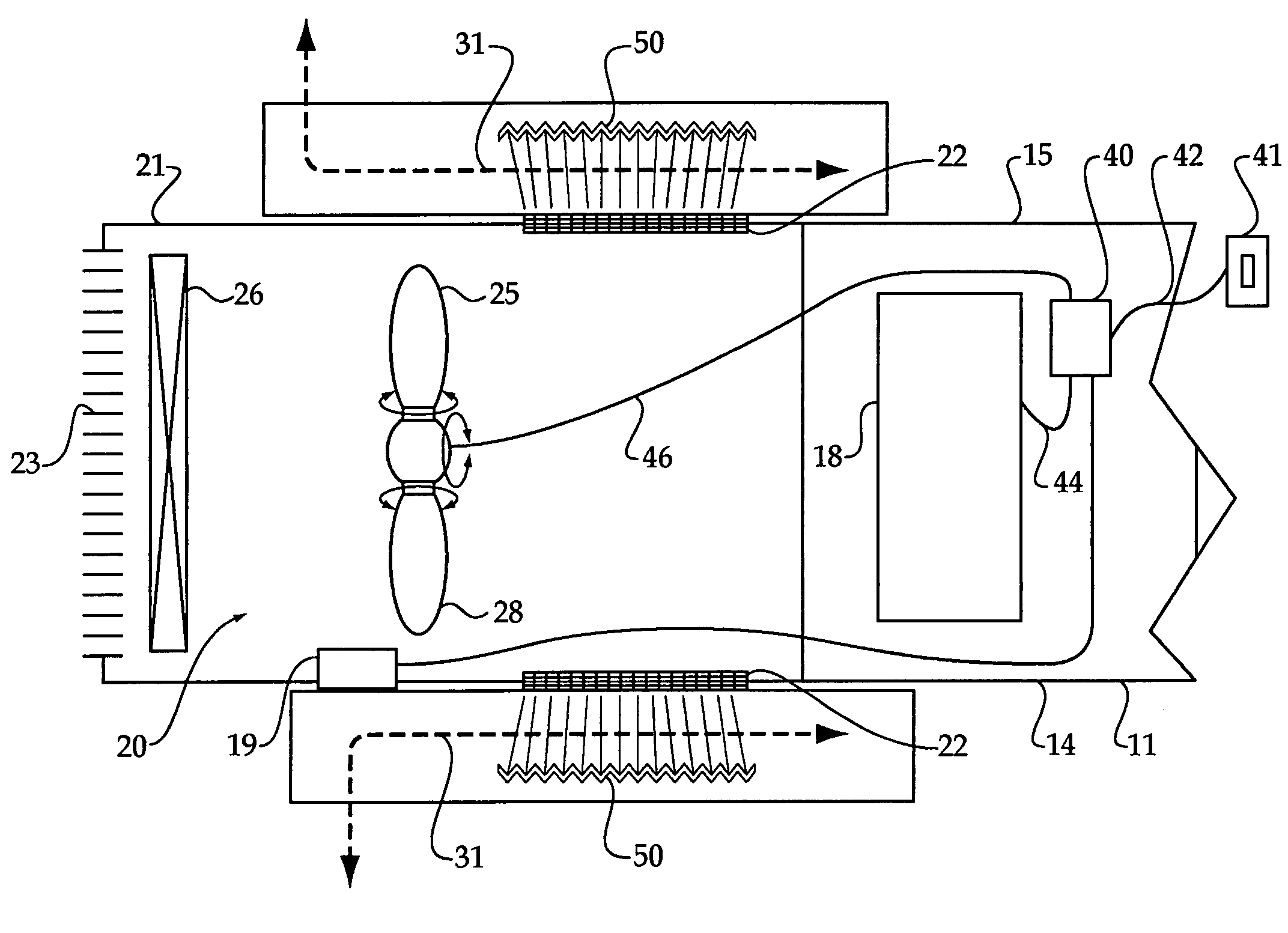
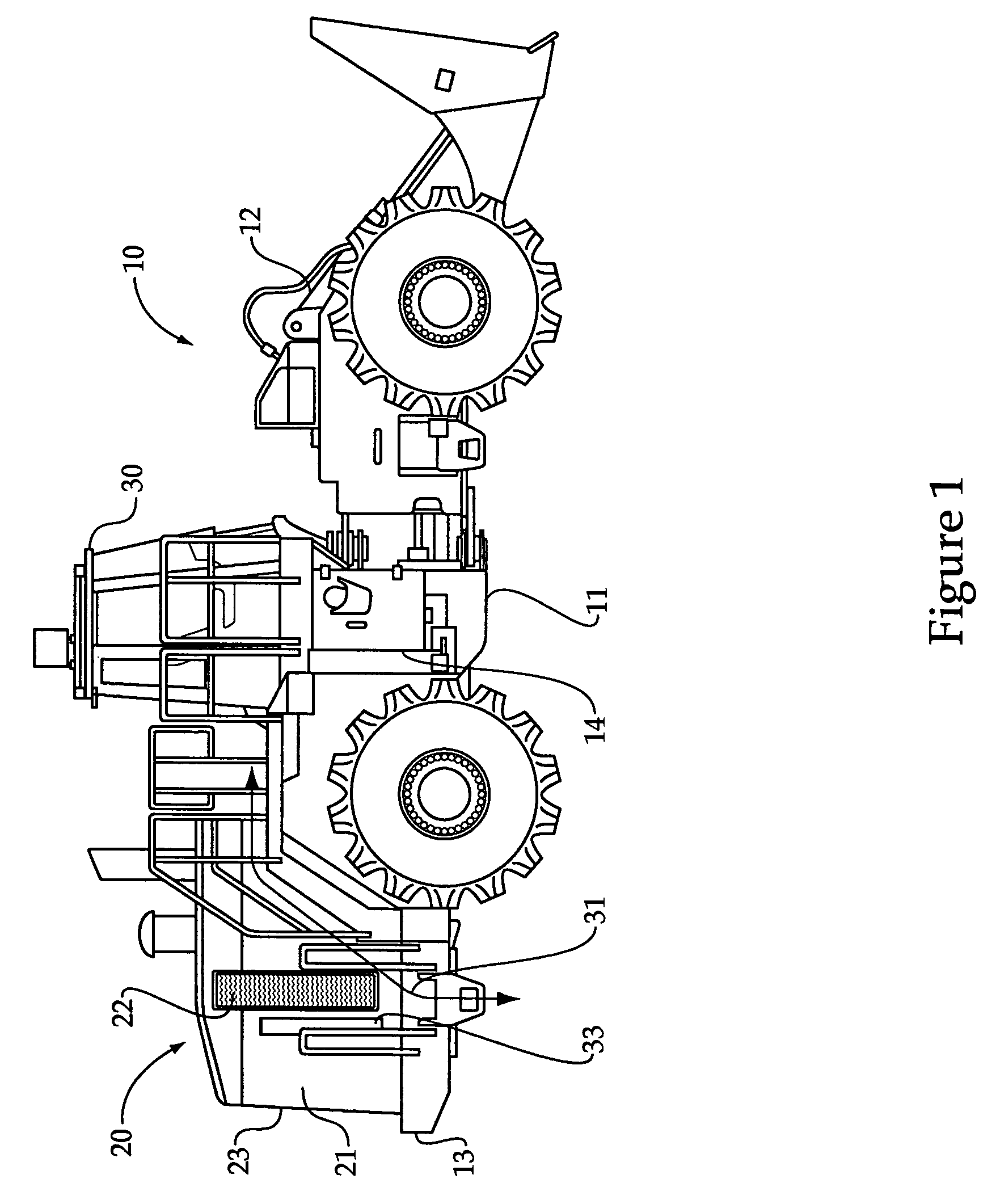
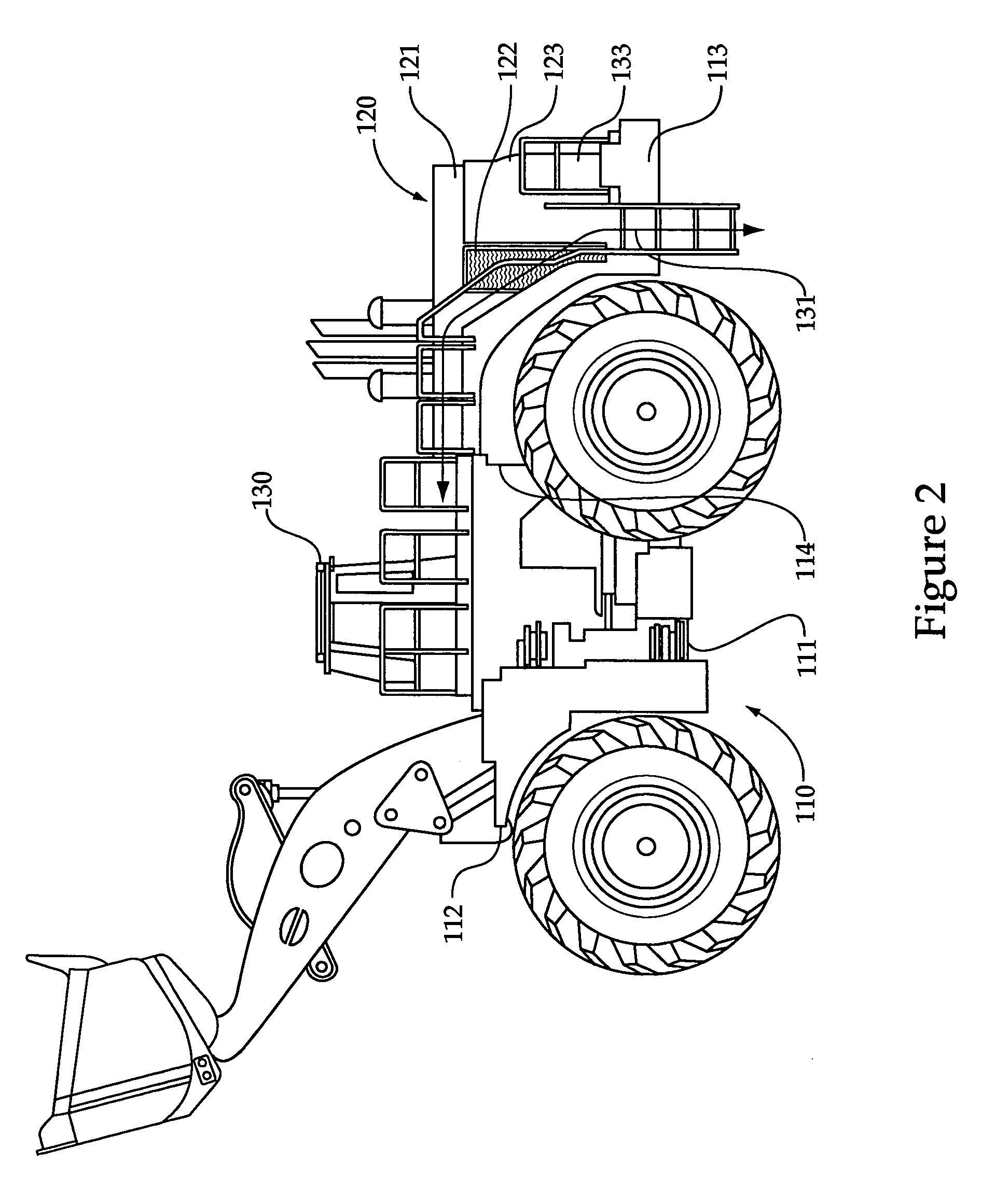
[0012]Referring to FIGS. 1 and 3, a landfill compactor machine 10 includes a chassis 11 with a front 12 separated from a back 13 by a first side 14 and a second side 15. Among other things, machine 10 may include a transmission 18, a parking brake 19, an air circulation system 20 and an operator station 30. The air circulation system 20 may include a fan and radiator positioned within a housing 21 between an air intake screen 22 and an outlet opening 23. Although the description refers to air intake screen 22 and outlet opening 23 in the singular, those skilled in the art will appreciate that there can be more than one of each without departing from the scope of the present disclosure. During normal operation, which may be referred to as a first operation configuration, a controller 40 controls fan 25 to pull air into housing 21 through air intake screen 22 and push the air through radiator 26 and out of housing 21 through outlet opening 23. Controller 40 may be configured in a mann...


PUM


Abstract

The air circulation fan associated with a radiator of some machines may include an automatic reversing purge cycle that is utilized to dislodge material from the radiator and / or intake screen of the cooling system housing. The purge cycle is locked out when a person may be in the vicinity of the air intake screen of the machine. A controller determines that a person may be in the vicinity of the air intake screen when the machine is idle stationary, such as by determining that a parking brake is engaged. By locking out the purge cycle during machine idle stationary conditions, the risk of blowing dislodged dirt and / or debris onto a person, who may be servicing the machine or accessing an operator station, can be avoided.

Description

TECHNICAL FIELD[0001]The present disclosure relates generally to reversing an air flow direction of a cooling fan to clear debris caught on an intake screen of a machine, and more particularly to locking out the air intake screen purge cycle when a person may be near the intake screen.BACKGROUND[0002]Many types of machines use an engine for motive power, and rely upon a radiator and an air circulation fan to assist in cooling the engine. The engine, radiator and fan are typically positioned within a housing that includes an air intake screen and an outlet opening. During normal operations, the fan draws air into the housing through the air intake screen, directs the air through the radiator and out of the housing through the outlet opening. In many types of applications, the machine may be working or traveling in a dirt and / or debris filled environment. As a result, materials such as dirt, insects, trash, leaves and the like can become lodged on the air intake screen. As material ac...

Claims


Application Information

Patent Timeline
Patent Type & Authority Patents(United States)
IPC IPC(8): H02P1/22F24F7/00
CPCF01P11/12
Inventor BECK, BRADLIN, HONG-CHINCHRISTIAN, JOEL
Owner CATERPILLAR INC
Why Eureka
Try Eureka