Thermal cycling resistant tube to header joint for heat exchangers

a technology of heat exchangers and tubes, applied in the field of heat exchangers, can solve the problems of dimensional changes in tubes and headers, failure of heat exchangers, and high undesirable failures, and achieve the effect of reducing material requirements and increasing the thermal cycle life of such heat exchangers

Inactive Publication Date: 2008-12-09
MODINE MFG CO
View PDF26 Cites 14 Cited by
  • Summary
  • Abstract
  • Description
  • Claims
  • Application Information

AI Technical Summary

Benefits of technology

[0012]It is the principal object of the invention to provide a new and improved heat exchanger of the type having tube to header joints. More specifically, it is an object of the invention to provide a significant increase in the thermal cycle life of such a heat exchanger while minimizing the material requirements of the solution as well as the assembly effort needed to implement it in heat exchanger production.

Problems solved by technology

As a result, dimensional changes in the tubes and headers occur as a result of the heating or cooling of the tubes and the header and the resulting thermal expansion or contraction.
These stresses in turn ultimately cause fatigue which is generally concentrated in the walls of the tube (since tube walls are typically thinner than headers and header flanges which may receive the ends of the tubes) until a fracture results causing leakage, and thus failure of the heat exchanger.
Such failure is highly undesirable.
Where the heat exchanger cannot be repaired, the same problem is present plus there is the additional cost of providing an entirely new heat exchanger to replace that which has failed.
While this approach works well, it adds to the cost of the heat exchanger because greater thicknesses mean that more material must be employed in the fabrication of the heat exchanger, thereby raising material cost.
While little is known about the effectiveness of this proposal, it has at least one clear drawback.
That is that each insert must be assembled to a tube end in individual operation thereby increasing assembly costs.

Method used


Image

  • Thermal cycling resistant tube to header joint for heat exchangers
  • Thermal cycling resistant tube to header joint for heat exchangers
  • Thermal cycling resistant tube to header joint for heat exchangers

Examples


Embodiment Construction

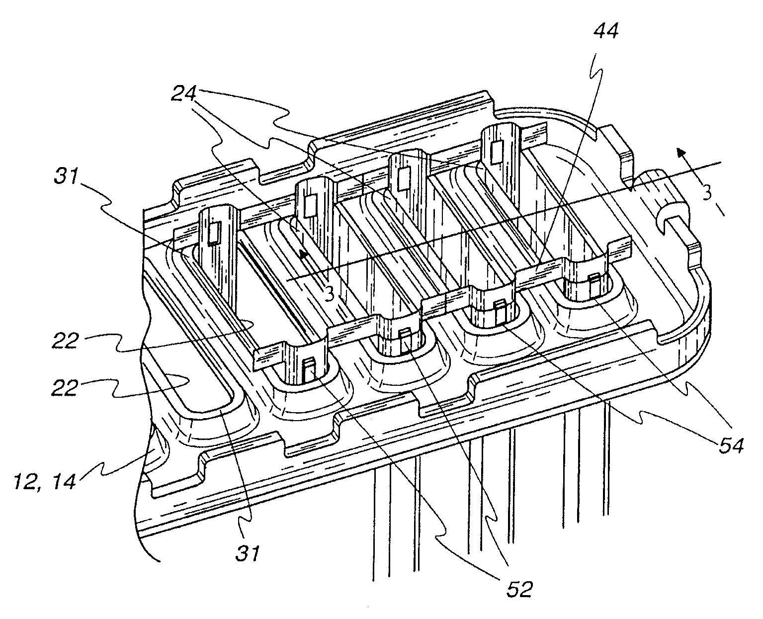
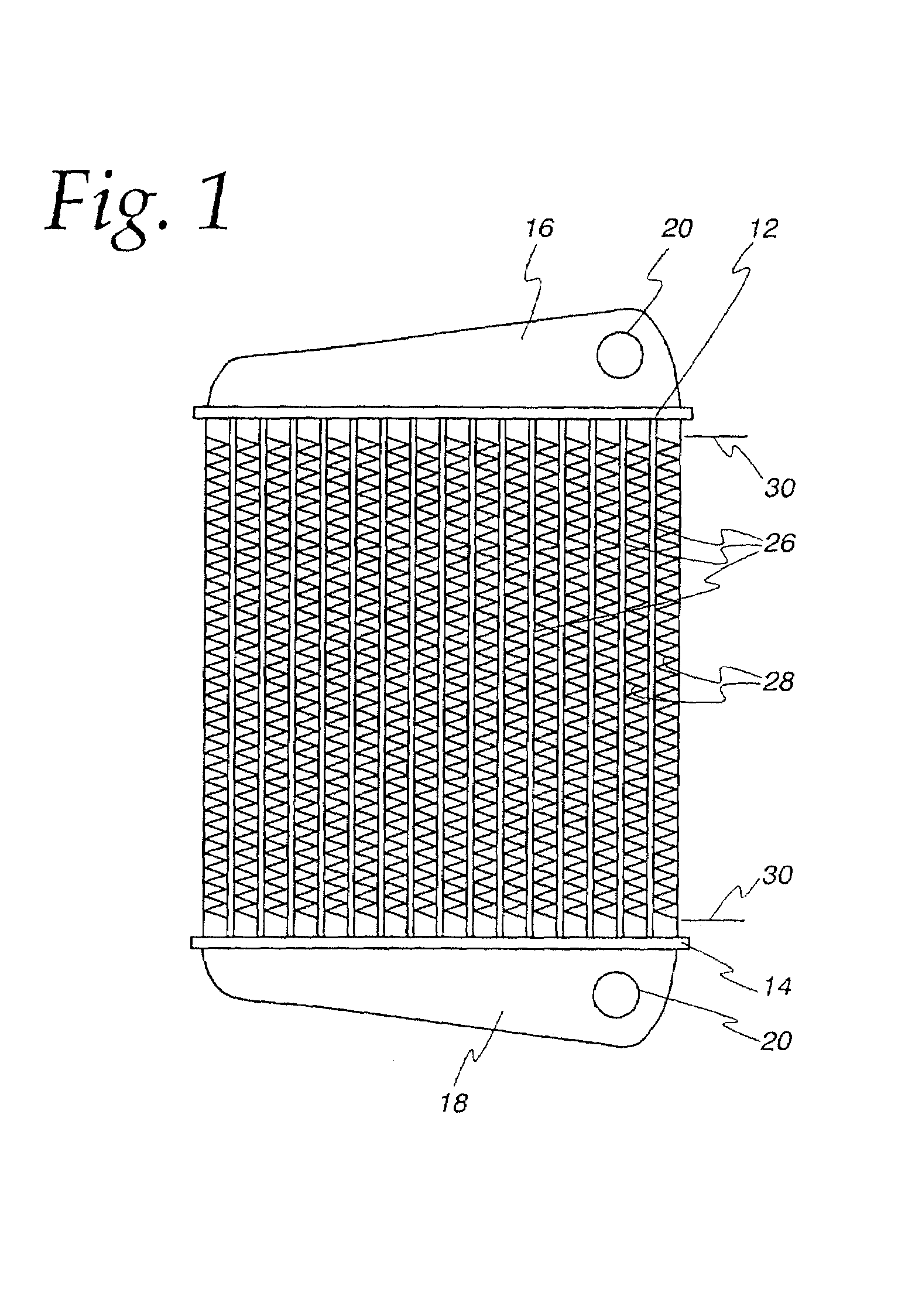
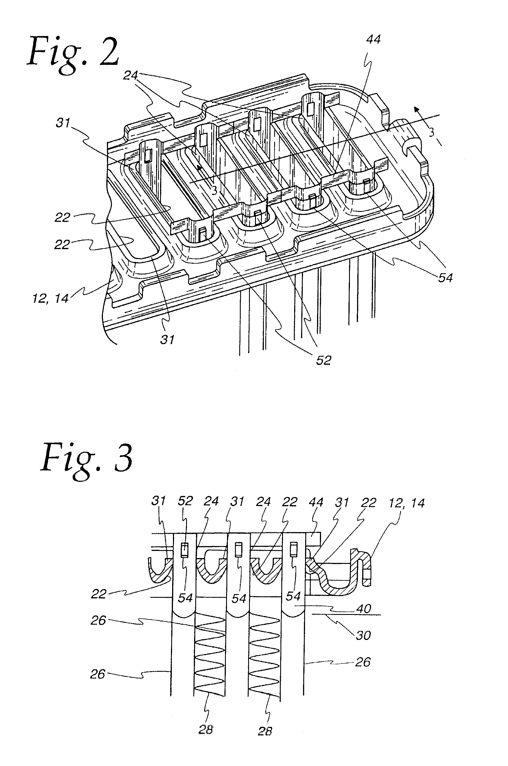
[0038]Exemplary embodiments of the invention will be described herein in the context of heat exchangers generally and no restriction to any particular use of the heat exchanger is intended except insofar as a expressly stated in the appended claims. However, it is to be noted that the invention can be utilized with its greatest efficacy in heat exchangers employing flattened tubes of relatively large minor dimension as for example, charge air coolers. Nonetheless, the invention may also usefully be employed in heat exchangers intended for other uses and having tubes with a relatively small minor dimension as, for example, vehicular radiators. The invention can be employed with flattened tubes of both the so-called fabricated type or the extruded type. Fabricated tubes are typically formed of fairly thin strip of metal formed upon itself with a welded seam and the greatest benefit of the invention is achieved when used with fabricated tubes. Nonetheless, no limitation to fabricated t...


PUM

PropertyMeasurementUnit
lengthaaaaaaaaaa
lengthaaaaaaaaaa
lengthaaaaaaaaaa

Abstract

A reduction in tube to header joint failures in a heat exchanger having spaced headers (12,14), elongated, side-by-side parallel spaced tube slots (22) in the headers (12,14) along the length thereof and a plurality of flattened tubes (26) having ends (24) received in the tube slots (22) and metallurgically bonded to the header (12,14) thereat was achieved through the use of a reinforcing structure (38) having at least two projections (40) having a cross sectional shape complimentary to at least a part of the surface of the tubes (26) at their ends (24) and a length sufficient to extend along the tube ends (24) to a location past the metallurgical bonds between the tube ends (24) and a header (12,14), and a spine (44) extending transverse to the projection. Also disclosed is a reinforcing structure (38) and a method of reinforcing the tube to header joints in a heat exchanger.

Description

FIELD OF THE INVENTION[0001]This invention relates to heat exchangers, and more particularly, to improved tube to header joints with increased resistance to failure as a result of thermal cycling.BACKGROUND OF THE INVENTION[0002]The art of heat exchange has been active for hundreds of years. One type of heat exchanger that has evolved over this time period is one that utilizes so-called tube to header joints. In this type of heat exchanger, two headers are typically located in spaced parallel relation. Each header is provided with a plurality of tube receiving apertures and the apertures in one header are aligned with corresponding apertures in the other. Tubes extend between and have their ends received in the headers. The ends are also sealed to the headers and then tanks are fitted to the headers in sealed relation to receive and confine a heat exchange fluid passing from the tank and header on one end of the assembly through the tubes to the tank and header on the other end of t...

Claims


Application Information

Patent Timeline
Patent Type & Authority Patents(United States)
IPC IPC(8): F28F9/007B23P15/26F28D1/00F28D1/053F28F1/00F28F9/00F28F9/02F28F9/04F28F9/18
CPCF28D1/05366F28F9/0224F28F9/185Y10T29/49373F28F2225/08Y10S165/906
Inventor MERKLEIN, BRIANINGOLD, ROY J.VERHAGEN, JEFFREYDO, TONY
Owner MODINE MFG CO
Why Eureka
Try Eureka