Eddy current speed reducer

A deceleration device and eddy current technology, applied in the direction of asynchronous induction clutch/brake, etc., can solve problems such as poor efficiency of installation and operation, corrosion, troublesome manufacturing of support mechanisms, etc.

Inactive Publication Date: 2005-02-02
ISUZU MOTORS LTD
View PDF1 Cites 0 Cited by
  • Summary
  • Abstract
  • Description
  • Claims
  • Application Information

AI Technical Summary

Problems solved by technology

When the brake drum thermally expands, since the diameter of the brake drum increases, the change in diameter is absorbed by moving the support arm (spoke) combined with one end of the brake drum radially outward relative to the hub portion, but the support The manufacture of the wrist support mechanism is cumbersome, so the efficiency of the installation operation is poor
[0004] In addition, in order to improve the braking force, good conductors such as copper are bonded to a part of the inner peripheral surface and both sides of the brake drum, but peeling due to thermal cycles and corrosion due to dissimilar metal bonding (mainly crystals) may occur. boundary corrosion)

Method used


Image

  • Eddy current speed reducer
  • Eddy current speed reducer
  • Eddy current speed reducer

Examples


Embodiment Construction

[0015] The eddy current speed reducer consists of a rotor with multiple magnets and a stator with a cooling device. During non-braking, since the clutch mechanism is disengaged and the rotor does not rotate, no leakage magnetic field occurs and heat loss can be reduced. Also, the thermal cycle life of the stator is improved.

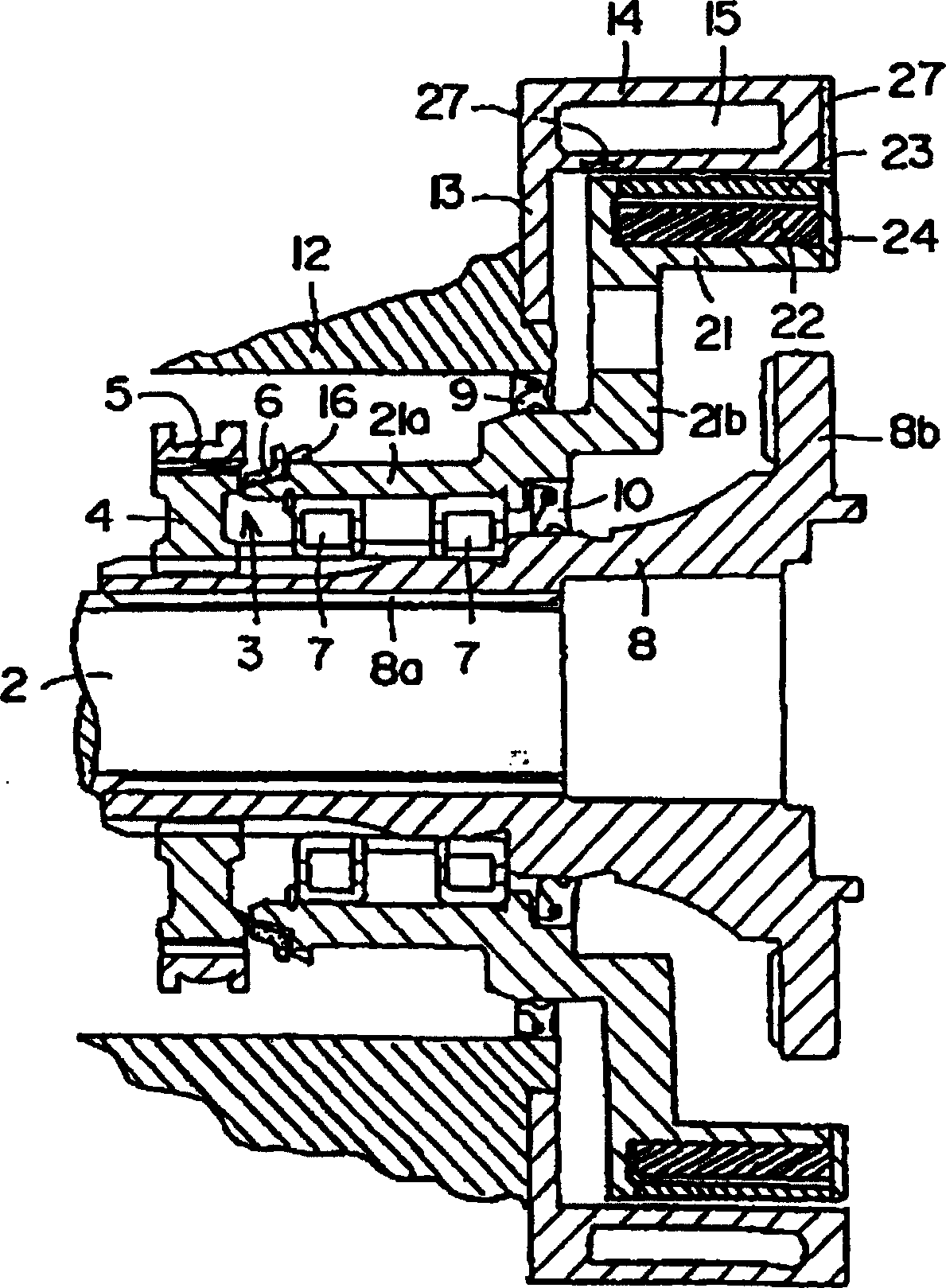
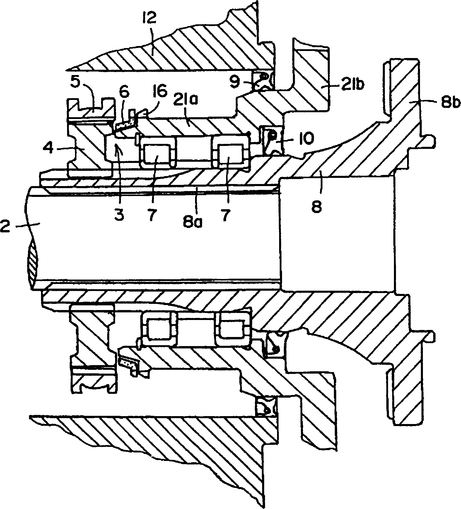
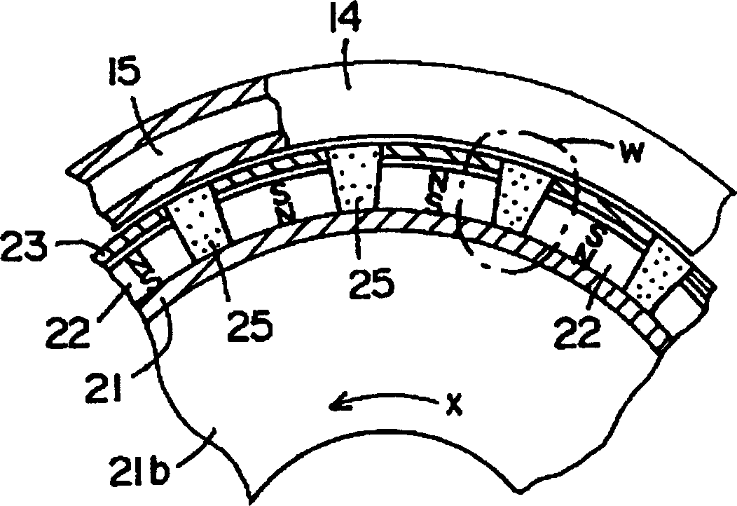
[0016] Such as figure 1 As shown, the embodiment in which the eddy current deceleration device of the present invention is installed on the output rotating shaft 2 of the transmission will be described. A rotor 21 in the shape of a rotor 21, magnets 22 coupled to the outer peripheral surface of the rotor 21 at equal intervals in the circumferential direction, and a cylindrical stator 14 formed of a magnetic material covering the rotor 21 are constituted. The stator 14 is configured by accommodating a cooling medium in an annular cooling chamber 15 and circulating the cooling medium from the outside. The end flange 13 of the stator 14 is joined to the ...


PUM


Abstract

The invention is able to enhance a lifetime of a heat cycle of a stator by reducing a heat loss by composing of a rotor combined to a magnet and a stator having a cooling unit, and by avoiding the rotor from rotating at a non-braking time. The cylindrical stator 14 formed from a ferromagnetic body is fixed to a non-rotating portion of a case 12 and the like of a speed changer, and a cylindrical rotor 21, which positions at the inside of the stator 14 and is formed from a magnetic body having a number of magnets 22 with an equal interval in its peripheral direction, is held to a rotating shaft 2 through a bearing 7. A clutch mechanism 3 is arranged between the rotating shaft 2 and the rotor 21. Then, the braking-time clutch mechanism 3 is connected so that an eddy current, based on the magnetic field that extends to the stator 14 from the magnets 22, shall generate a braking force at the rotor 21.

Description

technical field [0001] The present invention mainly relates to an eddy current deceleration device for assisting friction brakes of large trucks, especially an eddy current deceleration device for suppressing power loss during non-braking. Background technique [0002] The disclosed eddy current deceleration device of US Pat. The fuel consumption rate deteriorates. At this time, even if the magnet of the magnet support cylinder forms a magnetic circuit with a short circuit between the ferromagnetic plate (pole piece), the small magnetic field leaked from the ferromagnetic plate will cause damage to the brake drum. Drag torque is generated on the engine, which also causes deterioration in fuel consumption. [0003] On the other hand, when braking, the eddy current generated on the drum is converted into heat, causing the drum to thermally expand. When the brake drum thermally expands, since the diameter of the brake drum increases, the change in diameter is absorbed by movi...

Claims


Application Information

Patent Timeline
Patent Type & Authority Patents(China)
IPC IPC(8): H02K49/02
Inventor 浅野雅树
Owner ISUZU MOTORS LTD
Why Eureka
Try Eureka