Disk brake

a technology of disc brake and side brake, applied in the direction of brake types, actuators, brake elements, etc., can solve the problems of reducing the weight of the caliper, reducing the service life of the caliper, so as to achieve the effect of reducing the weigh

a technology of disc brake and side brake, applied in the direction of brake types, actuators, brake elements, etc., can solve the problems of reducing the weight of the caliper, reducing the service life of the caliper, so as to achieve the effect of reducing the weigh

US7461725B2Inactive Publication Date: 2008-12-09WABCO EURO BVBA SPRL

Image

  • Disk brake
  • Disk brake
  • Disk brake

Examples


Embodiment Construction

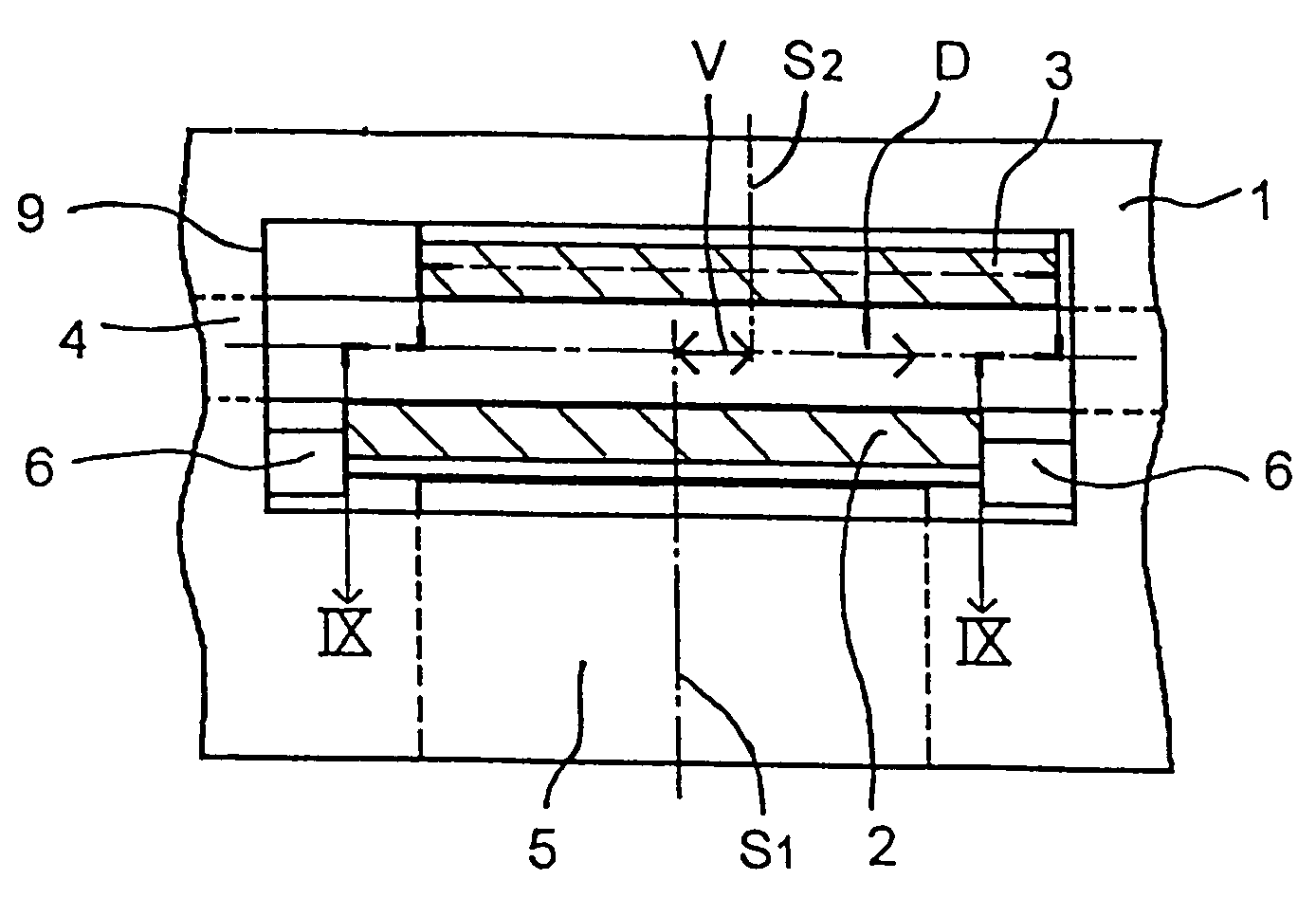
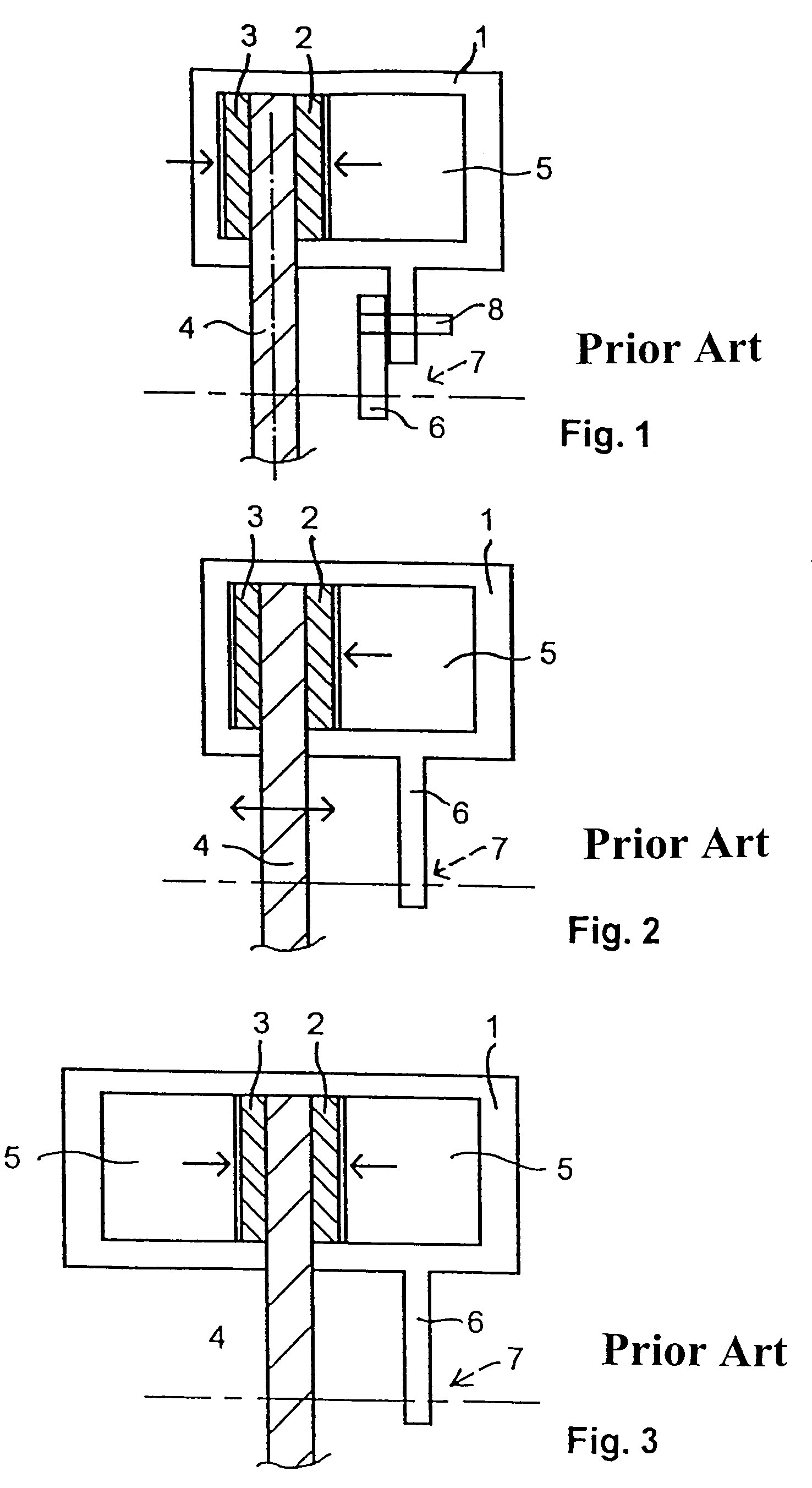
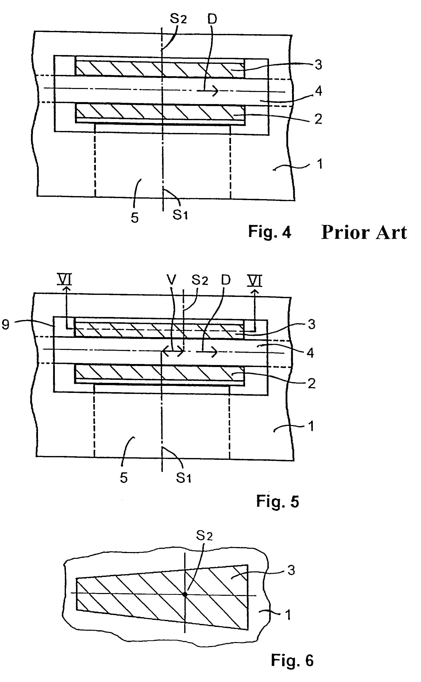
[0048]To the extent that they are present, the reference numbers used in FIGS. 5-9 are the same as those used in FIGS. 1-4.

[0049]As can be seen in FIGS. 5-9, the centers of gravity S1 and S2 do not coincide as they do in the state of the art. The corresponding offset is realized according to FIGS. 5 and 6 in that the contour of the facing of the brake pad 3 is designed so that its center of gravity S2 is offset from the center of gravity S1 of the brake pad 2 by a distance V toward the trailing side of the brake disk.

[0050]The offset V toward the trailing side of the brake disk, however, is preferably achieved by shifting the brake pad 3 in a parallel direction and / or by rotating it around an angle b in the free sidepiece of the caliper (FIGS. 7 and 9) with respect to the brake pad 2. The two centers of gravity S1 and S2 thus lie in any case on an imaginary arc of a circle around the center of the brake disk 4. This design offers the advantage that linings of the same design can be ...


PUM


Abstract

A disk brake includes a brake disk with a preferred rotational direction, with a first brake pad with a first center of gravity on a first side of the brake disk, a second brake pad with a second center of gravity on a second side of the brake disk, and a caliper for transmitting the braking forces produced by the second brake pad to the first side of the brake disk. The second center of gravity is offset from the first center of gravity by a predetermined distance in the direction toward the side of the brake disk that trails when the disk is rotating in its preferred direction.

Description

BACKGROUND OF THE INVENTION[0001]1. Field of the Invention[0002]The present invention relates to a disk brake[0003]with a brake disk having a preferred rotational direction;[0004]with a first brake pad with a first center of gravity on a first side of the brake disk;[0005]with a second brake pad with a second center of gravity on a second side of the brake disk; and[0006]with a caliper for transmitting the braking forces generated by the second brake pad to the first side of the brake disk.[0007]2. Description of the Related Art[0008]In general, the design and operation of disk brakes differ depending on the way the clamping device is installed in the brake caliper. FIGS. 1-4 show examples, namely:[0009]FIG. 1 shows a schematic cross-sectional view of a sliding caliper disk brake with one-sided clamping according to the reactive-force principle;[0010]FIG. 2 shows a schematic cross-sectional view of a fixed caliper disk brake with one-sided clamping according to the reactive-force pr...

Claims


Application Information

Patent Timeline
09 Dec 2008
Publication
US7461725B2
IPC
F16D65/00; F16D55/00; F16D65/092; F16D65/14
CPC
F16D65/092; F16D2055/0045; F16D2121/02; F16D2055/0079
Inventors
KLOOS, EUGEN; BEYER, FRANK