Apparatus for separating fibers from reject material

a technology for separating fibers and reject materials, applied in the direction of chemistry apparatus and processes, textiles and papermaking, etc., can solve the problems of difficult removal of fibers from the washing process, weak operation power of these apparatuses, and slow screening speed

Inactive Publication Date: 2008-12-09
VALMET TECH INC
View PDF9 Cites 10 Cited by
  • Summary
  • Abstract
  • Description
  • Claims
  • Application Information

AI Technical Summary

Benefits of technology

[0007]It is an object of the present invention to provide a very efficient apparatus for separating fibrous water from reject material produced in the manufacture of recycled pulp, which apparatus does not have the above drawbacks.
[0012]The invention provides the advantage that the apparatus of the invention is a compact reject treatment station and can separate the fibrous water to be used in different stages of the paper manufacturing processes and small, light and heavy reject particles efficiently from the suspension in the collecting basin. In addition, it is easy to control the operation of the apparatus, it is simple and inexpensive to manufacture and it washes the reject pulp in a more efficient way than known apparatuses so that it becomes very clean.

Problems solved by technology

However, the operating power of these apparatuses is quite weak and also the screening is fairly slow, especially if the casing part on the feed side of the apparatus does not have holes, since in that case the fibers cannot be washed away from the rest of the reject pulp efficiently.
A problem with these known solutions is that the screen cylinder rotating partly below the fluid level in the collecting basin causes a strong turbulence in the suspension in the basin, consisting of fibrous water and small, light and heavy reject material, whereby the heavy reject particles are prevented from landing on the bottom of the collecting basin and the removal thereof from the washing process becomes harder.
As a result, the heavy reject particles remain to circulate in the washing process, thus causing mechanical wear of the apparatuses and an increasing need for stopping the process because of the necessary service operations.

Method used


Image

  • Apparatus for separating fibers from reject material
  • Apparatus for separating fibers from reject material
  • Apparatus for separating fibers from reject material

Examples


Embodiment Construction

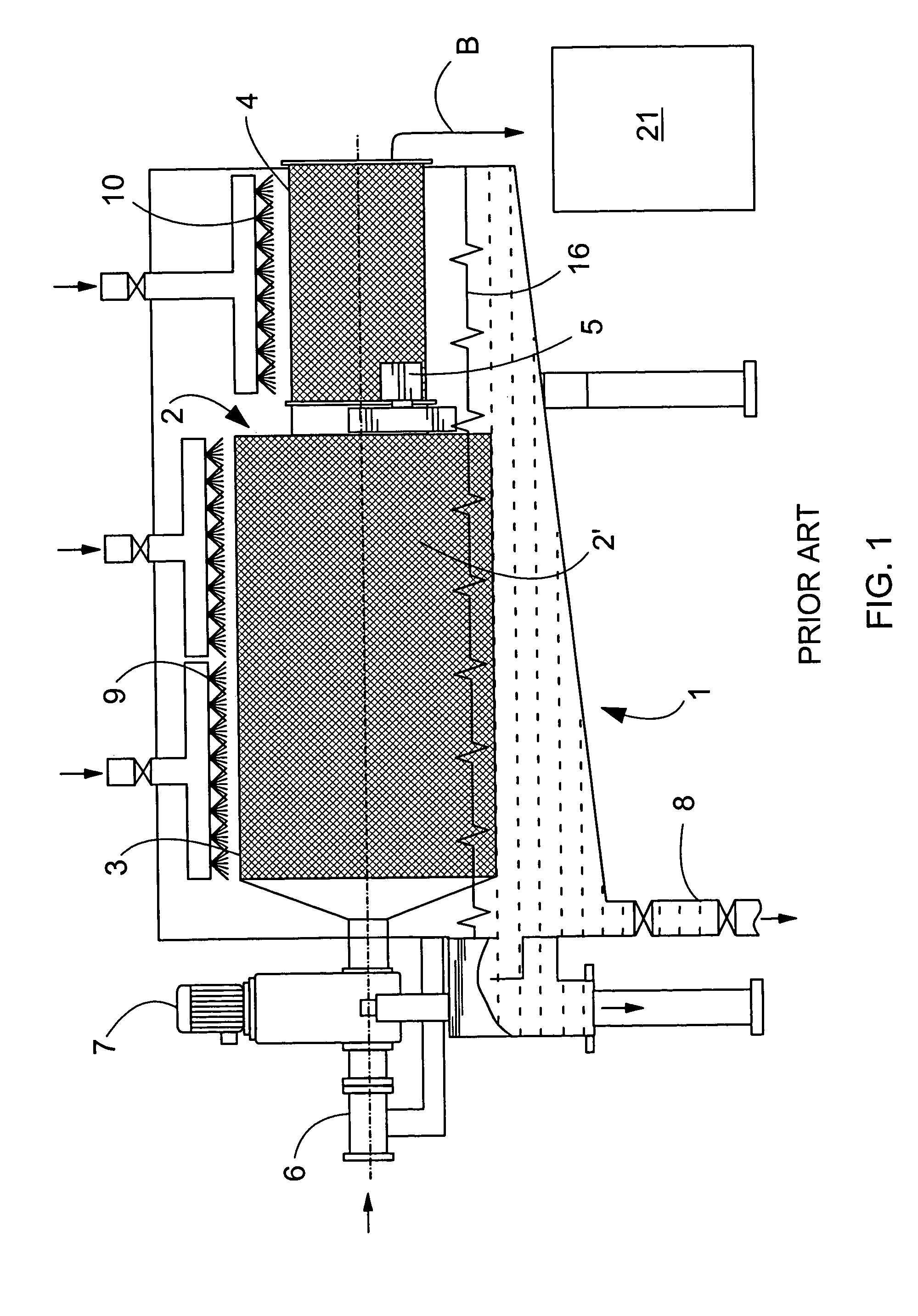
[0021]FIG. 1 shows schematically a structure of a prior art apparatus in longitudinal section. The apparatus comprises a collecting basin 1, above which there is a cylinder 2, which has a washing section 3 with a larger diameter and a drying section 4 with a smaller diameter. Both sections of the cylinder 2 comprise openings 2′, through which water and fiber can move. The cylinder 2 is mounted to rotate by means of a power apparatus 7 and supported on supporting rolls 5 and a feed pipe 6 which is connected coaxially to the washing section 3 of the cylinder and pivoted with respect to the frame in a rotating manner. The collecting basin 1 is inclined so that it becomes deeper towards the feed end of the washing section 3 of the cylinder 2, and it is connected with a waste discharge channel 8, by which small, heavy particles that have passed through the holes 2′ of the cylinder 2 of the washing section 3 can be removed. Above the washing section 3 of the cylinder 2 there are water fee...


PUM

PropertyMeasurementUnit
diametersaaaaaaaaaa
residence timeaaaaaaaaaa
diameteraaaaaaaaaa

Abstract

An apparatus for separating fibers from reject material produced in the manufacture of recycled pulp. The apparatus comprises a rotating reject cylinder provided with openings, to one end of which the reject material is fed and from the other end of which it is discharged, water nozzles for feeding water to the reject material in the cylinder to separate fibers from it, a collecting basin for recovering water and the fibers separated with it, and discharge channels connected with the collecting basin, and means for discharging fibrous water and light and heavy particles from the collecting basin. The collecting basin is formed of two basin structures at least partly within each other and connected with each other.

Description

BACKGROUND OF THE INVENTION[0001]1) Field of the Invention[0002]The present invention relates to an apparatus for separating fibers from reject material produced in the manufacture of recycled pulp, the apparatus comprising a rotating reject cylinder provided with openings, to one end of which the reject material is fed and from the other end of which it is discharged, water nozzles for feeding water to the reject material in the cylinder to separate fibers from it, a collecting basin for recovering water and the fibers separated with it, and discharge channels connected with the collecting basin, and means for discharging fibrous water and light and heavy particles from the collecting basin.[0003]2) Description of Related Art[0004]The use of recycled pulp becomes more and more common because of waste matter problems and to save forests. In the production of recycled pulp, among waste material there are various materials that are not desired in the paper and board manufacturing proc...

Claims


Application Information

Patent Timeline
Patent Type & Authority Patents(United States)
IPC IPC(8): B07B1/22B07B1/00D21BD21B1/32D21F1/74
CPCD21B1/32D21F1/74Y02W30/64
Inventor HAUTALA, JOUKOVUORINEN, TIMOHOURULA, ISMO
Owner VALMET TECH INC
Why Eureka
Try Eureka