
Internal arrangement of the walls of the fuselage of an aircraft

a technology of fuselage and interior arrangement, which is applied in the direction of aircraft floors, supersonic aircraft, air-treatment apparatus arrangement, etc., can solve the problems of cumbersome arrangement, complex arrangement, and long time-consuming to remove and refit in order to carry out maintenance or change parts of auxiliaries, so as to reduce the acoustic noise level in the cabin

Inactive Publication Date: 2008-12-09
EADS SOGERMA SERVICES
View PDF5 Cites 28 Cited by
  • Summary
  • Abstract
  • Description
  • Claims
  • Application Information

AI Technical Summary

Benefits of technology

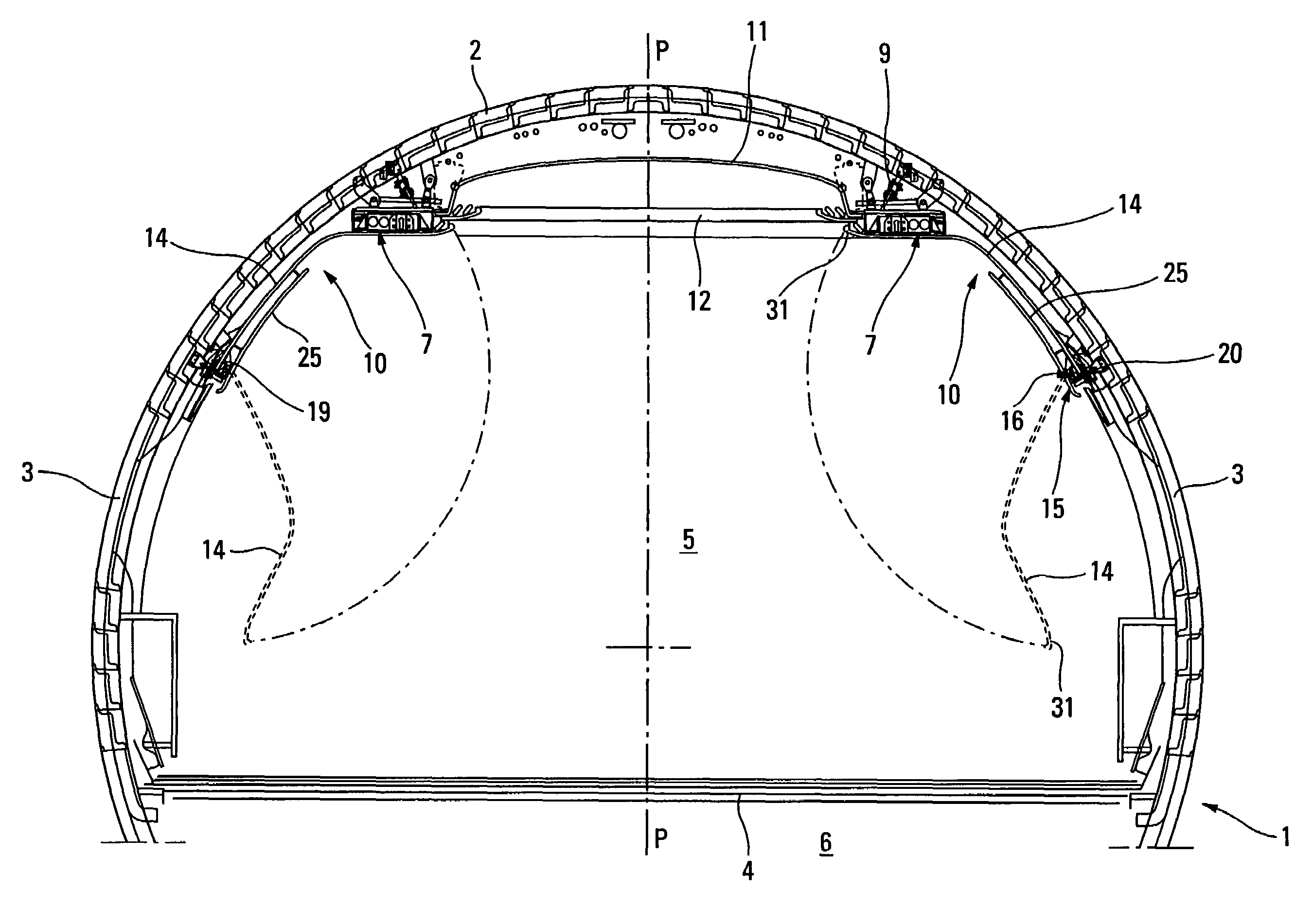
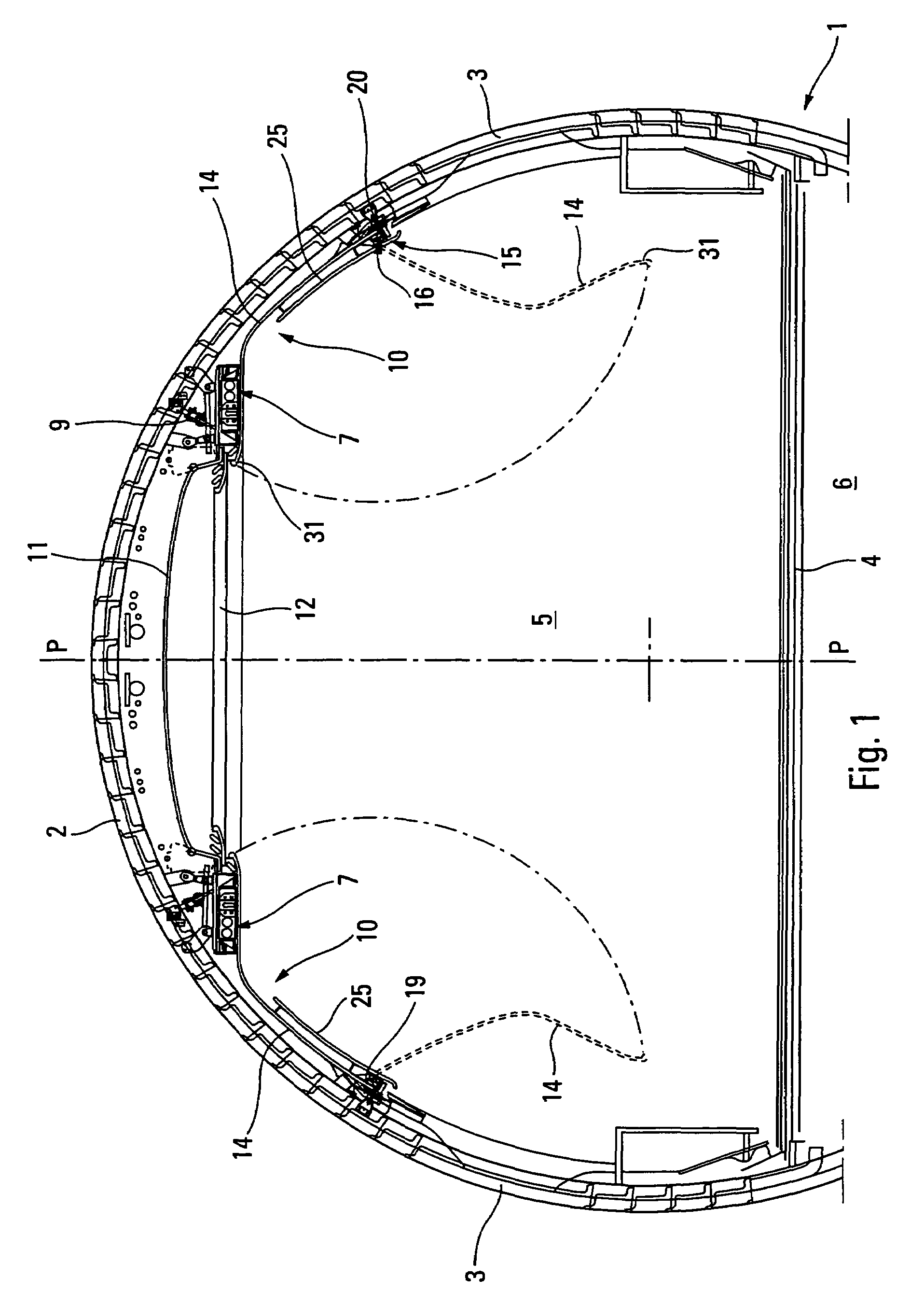
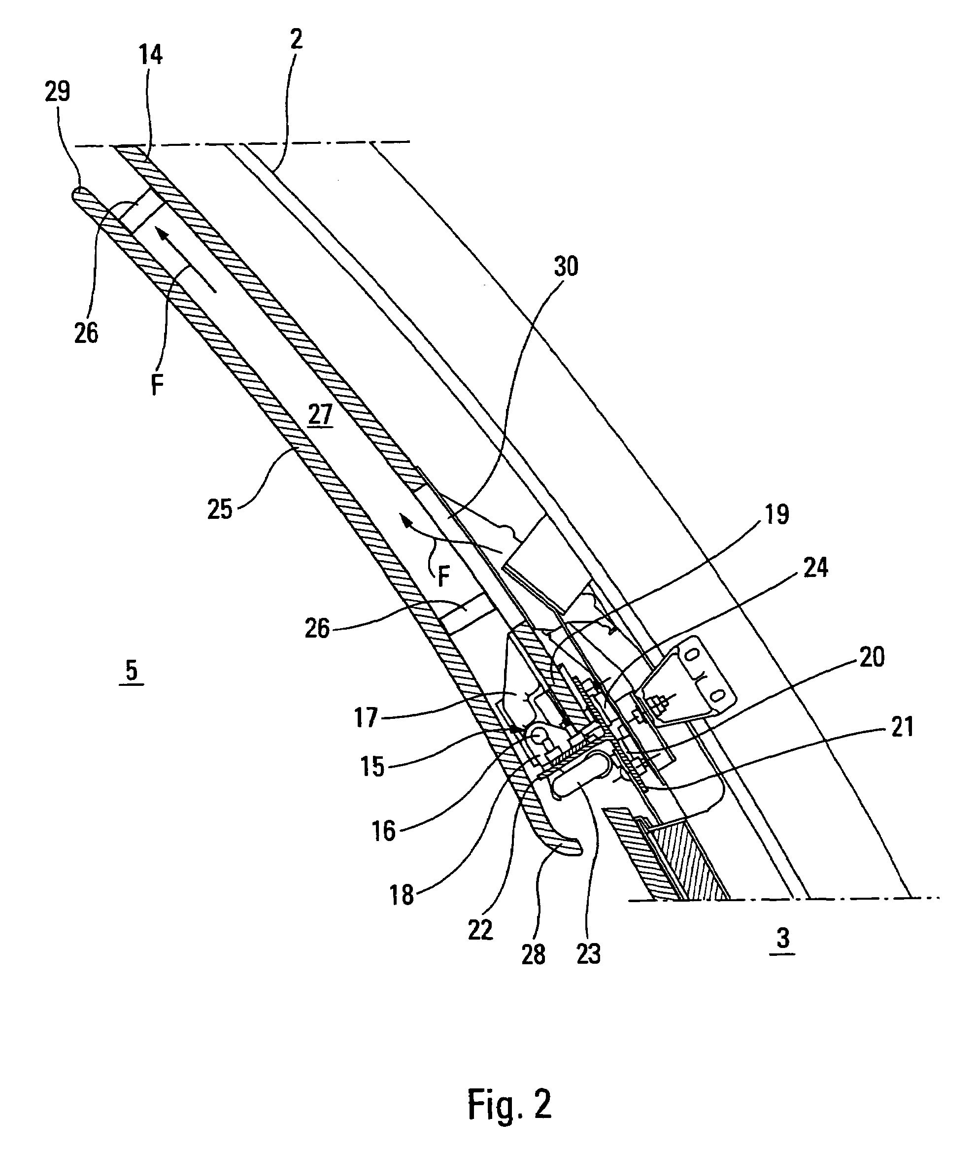
[0024]Thus, by virtue of the invention, by producing each cover assembly of the arrangement as a one-piece pivoting lateral panel, the latter can be disconnected from the corresponding structural duct, which means that work can be done on the auxiliaries inside said duct without removing the panel, making maintenance and inspection operations carried out on said duct, on the interior wall of the fuselage and on the flight equipment and wiring attached thereto easier. This is achieved by virtue of the pivoting nature of each panel that needs simply to be moved from the raised position into the lowered position in order to uncover the structural duct and gain access to the auxiliaries, fixings or the like concealed by the arrangement. Furthermore, the costs of manufacture are thereby greatly reduced and the weight saving is significant partly on account of the elimination of the fixings of the three parts that make up the assembly according to the prior art, on the walls of the fuselage and the structural duct. Producing the lateral panel as a single piece, more closely following the profile of the fuselage and of the duct, and extending its upper edge to conceal the edges and fixings of the ceiling panel and avoid unbecoming grooves, also contribute to improving the esthetic appearance of the cabin by giving the impression of a large volume.
[0027]For example, each lateral panel is connected, in its raised position, to its corresponding structural duct by quick latch / unlatch fixing means. Thus the “lateral panel—structural duct” connection is quick and easy to achieve.
[0032]Advantageously, in order to reduce the acoustic noise problems and reduce the acoustic noise level in the cabin, said structural ducts and said section pieces are fixed to the walls of said fuselage by damping elements.

Problems solved by technology

Because of the numerous screw or other connections and the parts involved in making up the arrangement, the sequences of removing and refitting in order to carry out maintenance or change parts of the auxiliaries are complicated, lengthy and involved.
Likewise, in order to access the dome, which is fixed to said ducts, and work on the circuits and the like situated in the space between the dome, the corresponding structural duct and the walls of the fuselage involved, it is necessary to take off the edging strips and the ceiling panel in question, then remove the dome fixings in order then to extract it between the two ducts in a movement which is tricky because it is fixed to these ducts (lifting it then tilting it in order to make it pass between the ducts) and risky.
It will be understood therefore that the excessive number of parts (particularly each covering assembly) and their arrangement (connection of the assemblies with the ducts, dome over the ducts, etc.) contribute to the complexity of the arrangement and to making this arrangement cumbersome.
In addition, esthetically, the visual presence of longitudinal grooves between the parts of the assemblies is unbecoming, and this is detrimental to a specifically luxury arrangement of the cabins for privileged passengers (VIPs).
In addition, the space available at the upper part of the cabin cannot be increased because of the fixed relationships between the assemblies and the structural ducts.

Method used


Image

  • Internal arrangement of the walls of the fuselage of an aircraft
  • Internal arrangement of the walls of the fuselage of an aircraft
  • Internal arrangement of the walls of the fuselage of an aircraft

Examples


Embodiment Construction

[0036]The fuselage 1 of an aircraft, depicted in FIG. 1, usually comprises assembled structural walls 2 schematically illustrated and incorporating side windows 3 and a floor 4 dividing the interior of the fuselage into an upper compartment 5 for the passengers and members of the crew, hereinafter referred to as the “passenger cabin”, and a lower compartment 6 for freight in particular.

[0037]In a known way, provided in the space delimited by the passenger cabin 5 are two structural ducts 7 running in parallel along the fuselage and arranged at the upper part thereof and respectively on each side of the vertical longitudinal plane of symmetry P of said fuselage. Running along and fixed to these structural ducts 7 which are spaced apart parallel to one another are various technical installations, not depicted in the figures, intended for ventilation, illumination, audio-video equipment, oxygen, etc. Each duct 7 is produced in particular from assembled metal components 8 and has, in cr...


PUM


Abstract

An internal arrangement of aircraft fuselage walls supports two longitudinal auxiliary passage ducts at the upper part of the fuselage and on each side of its longitudinal plane of symmetry. The arrangement includes a longitudinal central element forming a dome connecting the structural ducts, an interior ceiling panel situated under the dome and facing toward the cabin, and two lateral cover panels. A lower edge of each lateral panel is articulated with respect to the fuselage so that it may occupy a raised position in which it is connected to a respective one of the structural ducts near an upper edge of the structural duct and a lowered position in which it is distant from the structural duct. Also, the upper edge of each lateral panel is extended, in the raised position, beyond the structural duct to cover the corresponding longitudinal edges of the dome and the ceiling panel.

Description

FIELD OF THE INVENTION[0001]The invention relates to an internal arrangement of the walls of the fuselage delimiting the passenger cabin of an aircraft and, more particularly, to a luxury internal arrangement of the cabin.BACKGROUND OF THE RELATED ART[0002]It is known that the internal arrangement of the passenger cabin of an aircraft is dependent on certain technical installations necessary for the correct operation of the aircraft and for the comfort of the passengers and that run through its fuselage. Also, in order to create enough cabin space, these installations are attached along the walls of the fuselage and, in particular, in the upper part. In general, two longitudinal structural ducts spaced apart parallel to one another are supported by fixings at the upper parts of the walls of the fuselage, respectively on either side of the longitudinal plane of symmetry of the fuselage. These ducts accommodate the auxiliaries concerned, that is to say the installations relating in pa...

Claims


Application Information

Patent Timeline
IPC IPC(8): B64C1/00B64C1/06B64C1/12
CPCB64C1/066Y02T50/46Y02T50/40
Inventor SCHWARTZ, BRUNOTANGUY, RICHARDQUESNEL, JACQUESMUNCH, FRANCIS
Owner EADS SOGERMA SERVICES
Learn More