
Drive unit, preferably an actuator, a control and a construction

Inactive Publication Date: 2010-12-07
LINAK AS
View PDF16 Cites 2 Cited by
  • Summary
  • Abstract
  • Description
  • Claims
  • Application Information

AI Technical Summary

Benefits of technology

[0014]There is no evident explanation to the phenomenon, but a possible explanation is that the reason is the reduction in the variation of the moment supplied by the motor, thereby producing a more constant engagement of the individual parts of the transmission. This, in turn, leads to smaller vibrations in the motor and the transmission as well as the structure as a whole, and thereby the acoustic noise is reduced.
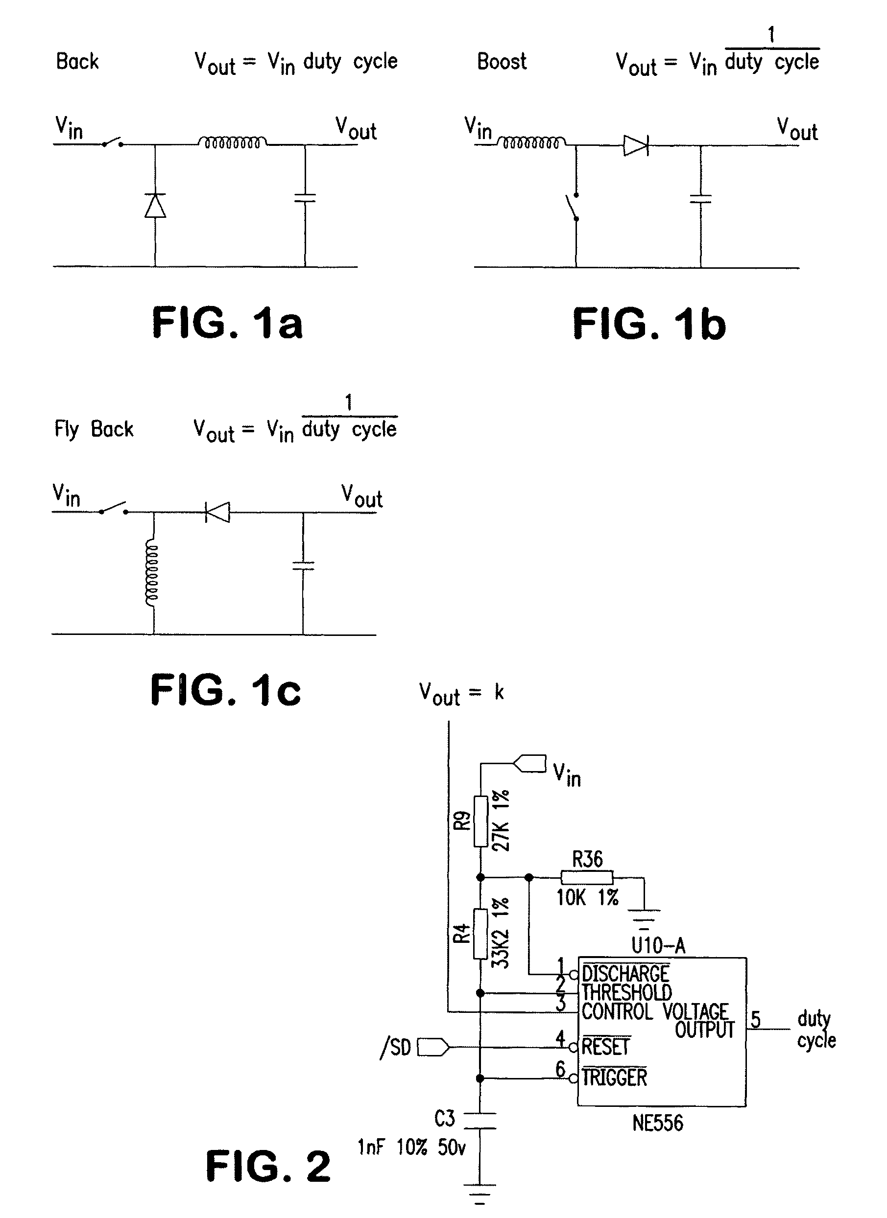
[0016]A particularly favourable embodiment of the second control adapted to remove the ripple in the voltage is characterized in that the smoothing is performed by the following two steps, viz. a forward step and a power step, where the forward step may be described as the input voltage Vin from the rectification and a constant which is given by the actual embodiment of the circuits for the two steps. The power step may be described by its output voltage Vout and the input voltage Vin and the duty cycle which is the proportional time for which the power supply may be loaded during a given period of time. The result of the two steps gives Vout=k, i.e. the smoothed voltage is constant. This structure is entirely or practically entirely free of ripple voltage and simultaneously has a high efficiency and is moreover simple and inexpensive.
[0019]Another possibility is a linear control which is characterized by a low-cost, ripple-free and simple structure, but the power loss is quite great.

Problems solved by technology

Especially in the furniture business, a decisive aspect is the level of noise, and with a demand for less expensive actuators it is even more difficult to meet the requirement for low-level noise actuators.
During adjustment of the article of furniture mechanical noise occurs, such as transmission noise, noise in the suspension of the adjustable element, noise because of vibrations that propagate in the structure, etc.
When the most powerful single sources of noise have been remedied, it is a complex noise picture that emerges, it being very difficult, if not impossible, to locate the individual sources of noise.
Some of the noise originates from the motor, where part of the noise is caused by the structure of the rotor with axis-parallel air gaps between the iron flanges on which the coils are wound.
This gives small, but noticeable discontinuities in the magnetic field that cause vibrations which propagate in the structure and cause acoustic noise.
Another part of the noise from the motor is caused by an axial movement of the rotor, which likewise results in vibrations and thereby acoustic noise.
Owing to manufacturing tolerances it is difficult to do anything about the problem.
Another aspect of the acoustic noise is the transmission noise, part of which originates from the engagement between the gear wheels or more particularly the varying degree of the engagement.
The outlined solutions are expensive and complicated or cannot readily be implemented in the present connection.

Method used


Image

  • Drive unit, preferably an actuator, a control and a construction
  • Drive unit, preferably an actuator, a control and a construction
  • Drive unit, preferably an actuator, a control and a construction

Examples


Embodiment Construction

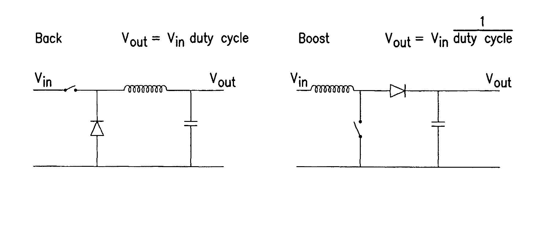
[0029]The first example is a Buck circuit, which may be expressed by Vout=Vin·duty cycle. The corresponding forward step must be duty cycle=k / Vin. The result is then Vout=k.

[0030]The next example is a boost circuit, which may be expressed by Vout=Vin / duty cycle. The corresponding forward step must be duty cycle=Vin / k. The result is then again Vout=k.

[0031]The third example is a flyback circuit, which resembles the preceding one, but with the opposite sign Vout=−Vin / duty cycle. The same forward step as before may be used, viz. duty cycle=Vin / k, which gives Vout=−k.

[0032]FIG. 2 shows a forward step which may be used in connection with all three examples of power steps, with just a dimensional adaptation to the examples shown. It is seen to include an NE556 astable timer having a duty cycle directly controlled by output voltage with adjustments from input voltage.

[0033]It will be appreciated that the invention is not limited to the mentioned circuits, and that other circuits fulfilling...


PUM


Abstract

In particular in articles of furniture having at least an element which may be adjusted with a DC motor, preferably via a mechanical transmission, it is desirable to have a level of acoustic noise as low as possible. The power supply to the DC motor is based on a transformer with rectification and smoothing. With the invention it has surprisingly been found that the level of acoustic noise may be reduced significantly in that the secondary side of the transformer has a first control to compensate for the loss in the motor, thereby keeping the speed thereof constant for a long period of time, and a second control adapted to remove the ripple in the voltage, thereby keeping the speed of the motor constant for a short period of time.

Description

BACKGROUND OF THE INVENTION[0001]1. Field of the Invention[0002]The present invention relates to a drive unit for moving parts of articles of furniture.[0003]2. The Prior Art[0004]Actuators driven by a reversible low volt DC motor, typically 24V, are used for adjustable articles of furniture, such as beds, chair and tables. In a linear actuator, the motor, via a transmission, drives a spindle having a nut fixed against rotation so that the nut can move to and fro on the spindle depending on the direction of rotation of the spindle. The nut has arranged thereon a tubular rod whose free end is provided with an attachment for securing in the structure. Typically, the transmission simply consists of a worm gear, where the worm is provided in an extension of the motor shaft and the worm wheel secured directly on the spindle. An example is disclosed in WO 02 / 29284 to Linak A / S. A special structure of linear actuators is called lifting columns, e.g. intended for table legs. Rotary actuator...

Claims


Application Information

Patent Timeline
IPC IPC(8): H02P1/54H02P5/46H02P5/00H02P7/28
CPCH02P7/28
Inventor BASTHOLM, JEPPE
Owner LINAK AS
Learn More