Selectively annealed bumper beam

a bumper beam and selective annealing technology, applied in the field of tubular bumper beams, can solve the problems of aggravated problems, difficult to make the cross section small enough, sharp bends, and limit the forming that can be done to the rollformed section, and achieve the effect of optimizing the impact characteristics and reducing tensile strength

Inactive Publication Date: 2008-12-09
SHAPE CORP
View PDF26 Cites 9 Cited by
  • Summary
  • Abstract
  • Description
  • Claims
  • Application Information

AI Technical Summary

Benefits of technology

[0005]In one aspect of the present invention, a bumper system includes a tubular beam formed from ultra-high-strength steel of at least 80 ksi tensile strength. The tubular beam is tubular for an entire length and includes a center section, end sections, and mounting sections connecting the center section to the end sections. Brackets are attached to the mounting sections, the brackets being adapted for connection to vehicle frame rails. At least one portion of one of the center section, the end sections, and the mounting sections are annealed to have a reduced tensile strength of less than 80 ksi, thus optimizing impact characteristics of the beam.

Problems solved by technology

However, due to the limited elongation associated with UHSS materials, there is a limit to the forming that can be done to the rollformed section before material cracking occurs.
This limitation can provide challenges to packaging a rollformed cross section into the required space provided by the original equipment manufacturer (OEM).
Specifically, it is difficult to make the cross section small enough and the bends sharp enough to meet OEM space and shape requirements.
This problem is aggravated when the beam has a longitudinal curvature / sweep.
However, Nees '931 does not teach where or how to apply this technology to bumper beams, nor to tubular reinforcement beams where the entire beam is tubular.

Method used


Image

  • Selectively annealed bumper beam
  • Selectively annealed bumper beam
  • Selectively annealed bumper beam

Examples


Embodiment Construction

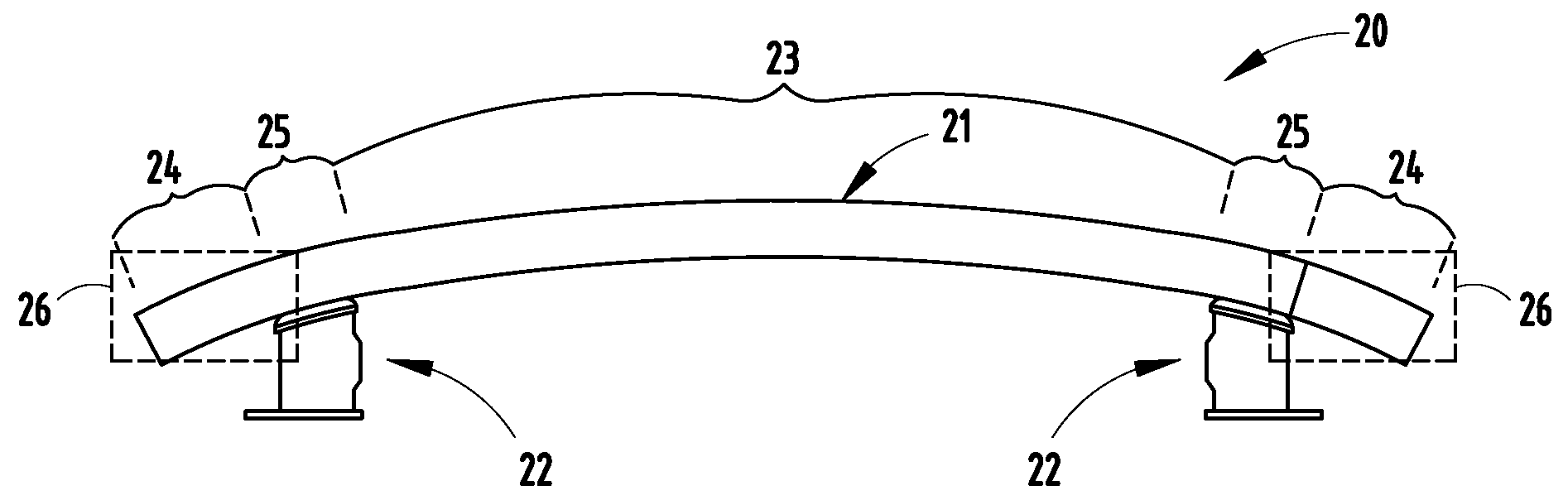
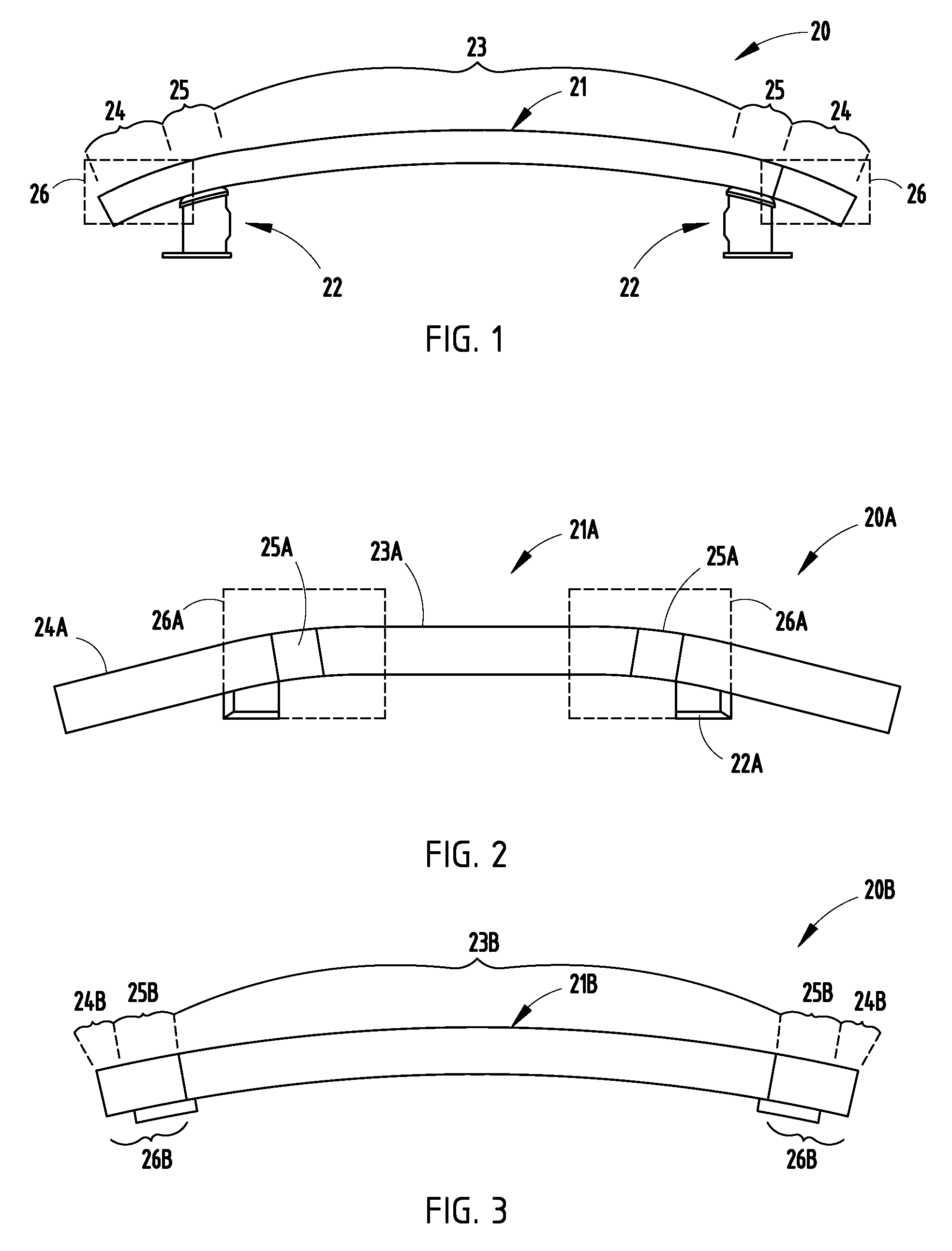
[0014]Bumper system 20 (FIG. 1) includes a tubular beam 21 with bracket mounts 22 welded to a rear surface of each tubular end of the beam 21 for mounting the beam 21 to vehicle frame rails. The illustrated beam 21 is rollformed to have a continuous cross section and is tubular for its entire length, though it is contemplated that aspects of the present invention can be incorporated into other beam shapes. The illustrated beam 21 has a center section 23 with a front face defining a relatively large first radius (such as 2500 mm), and corner-forming end sections 24 with a front face defining a relatively smaller second radius (such as 425 mm). A mounting section 25 connects the ends of the center section 23 with the end sections 24, and provides the structure for attachment of the mounts 22. Thus, the beam 21 has an increasingly curved front face near its ends, adapting it for use in a vehicle having an aerodynamically-shaped front end. Notably, the beam 21 can be “D” or “B” shaped (...


PUM

PropertyMeasurementUnit
tensile strengthaaaaaaaaaa
radiusaaaaaaaaaa

Abstract

A bumper system includes a rollformed tubular beam with bracket mounts welded to a rear surface for mounting to vehicle frame rails. The illustrated beam has a continuous tubular cross section for its entire length, and includes a center section, corner-forming end sections, and mounting sections connecting ends of the center section to the end sections. The center, end and mounting sections can be linear or similarly curved or differently curved. The center, end and mounting sections can be similarly or differently locally annealed as part of being tuned to specific impact loading criteria, including annealing all or part of cross-sectional areas. The annealing can be done in-line with a rollforming process, such as to assist with forming tight radii in the beam for meeting packaging / space-related requirements, or can be part of a secondary process for advantageously affecting impact strengths in selected localized areas.

Description

[0001]This application claims benefit under 35 U.S.C. § 119(e) of provisional application Ser. No. 60 / 823,926, filed Aug. 30, 2006, entitled SELECTIVELY ANNEALING BUMPER BEAM, the entire contents of which are incorporated herein in their entirety.BACKGROUND[0002]The present invention relates to tubular bumper beams useful in bumper systems, such as for the front and rear of vehicles. However, it is contemplated that aspects of the present invention are not limited to only front and rear bumper beams, as described below.[0003]Tubular rollformed bumper beams manufactured from ultra-high-strength steel (UHSS) material with high-tensile strengths (such as materials having 140 ksi tensile strength) provide excellent impact characteristics and high strength-to-weight ratios. However, due to the limited elongation associated with UHSS materials, there is a limit to the forming that can be done to the rollformed section before material cracking occurs. This limitation can provide challenges...

Claims


Application Information

Patent Timeline
Patent Type & Authority Patents(United States)
IPC IPC(8): B60R19/03
CPCB60R19/18Y10T29/49622B60R2019/1826
Inventor GUILES, MELVINNEES, RAINER B.HEATHERINGTON, DAVID W.JOHNSON, THOMAS J.
Owner SHAPE CORP
Why Eureka
Try Eureka