Furcation tubing and fanout furcation kit

a technology which is applied in the field of furcation tubing and kit, can solve the problems of inability to adjust, excessive longitudinal shrinkage of pvdf furcation tubing, and inability to achieve satisfactory tensile strength, and achieves the effect of reducing longitudinal shrinkage, preventing movement of optical fibers, and increasing tensile bonding strength

Active Publication Date: 2008-12-09
CORNING OPTICAL COMM LLC
View PDF12 Cites 99 Cited by
  • Summary
  • Abstract
  • Description
  • Claims
  • Application Information

AI Technical Summary

Benefits of technology

[0009]To achieve the foregoing and other objects, and in accordance with the purposes of the invention as broadly described herein, the present invention provides various embodiments of furcation tubing having reduced longitudinal shrinkage and increased tensile bond strength. The present invention also provides various embodiments of a fanout furcation kit that prevents movement of the optical fibers as a result of exposure to extreme temperatures and temperature cycling. In the various exemplary embodiments shown and described herein, the improved furcation tubing and the improved fanout furcation kit significantly reduce the likelihood of unacceptable attenuation and micro-damage to optical fibers deployed in an outdoor fiber optic network. In addition, the present invention also provides improved manufacturing process capabilities and reduced manufacturing and assembly times, along with generally enhanced mechanical strength and environmental performance in certain outdoor installations.

Problems solved by technology

Although each of these materials provides certain advantages, both have one or more undesirable characteristics when used in conjunction with fanout furcation kits and fiber optic connectors or optical devices.
PVDF furcation tubing, however, experiences excessive longitudinal shrinkage when exposed to the extreme temperatures and / or temperature cycling encountered in some outdoor installations.
Excessive shrinkage can cause unacceptable attenuation (i.e., transmission loss) due to micro-bending of the optical fibers within the furcation tubing and movement of the optical fibers within the fanout furcation kit, fiber optic connector or optical device.
In some instances, however, factory pre-conditioning has been insufficient to prevent unacceptable attenuation and micro-damage to optical fibers in fanout furcation kits deployed in some outdoor installations.
PTFE furcation tubing, however, has certain other undesirable characteristics for use with fanout furcation kits and fiber optic connectors or optical devices.
In addition, PTFE furcation tubing is not readily available in the twelve standard colors utilized in the telecommunications industry for fiber identification.
However, existing fanout furcation kits filled with an epoxy or acrylate continue to experience unacceptable attenuation and micro-damage to optical fibers installed in an outdoor fiber optic network.
In some instances, the epoxy or acrylate drains out of the funnel area during the cure cycle, resulting in insufficient adhesion to the optical fibers, or exposure of the optical fibers to the ambient environment.
More viscous epoxies and acrylates have been used to reduce drainage with only limited success since a more viscous epoxy or acrylate increases the likelihood of developing voids that reduce adhesion and expose the optical fibers to the ambient environment.
In other instances, the optical fibers are not fully encapsulated by the epoxy or acrylate since some of the optical fibers are positioned immediately below another optical fiber, and thus, are not readily visible during assembly, while the funnel area is being filled with the epoxy or acrylate, and after the epoxy or acrylate is cured.

Method used


Image

  • Furcation tubing and fanout furcation kit
  • Furcation tubing and fanout furcation kit
  • Furcation tubing and fanout furcation kit

Examples


Embodiment Construction

[0030]The present invention will now be described more fully hereinafter with reference to the accompanying drawings in which exemplary embodiments of the invention are shown. However, the invention may be embodied in many different forms and should not be construed as limited to the embodiments set forth herein. These exemplary embodiments are provided so that this disclosure will be both thorough and complete, and will fully convey the broad scope of the invention to those skilled in the art. Like reference numbers refer to like elements throughout the various drawings.

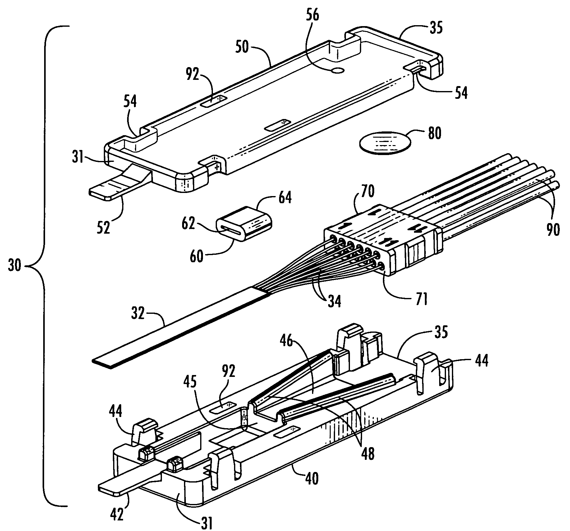
[0031]The various embodiments shown and described herein provide furcation tubing for transitioning a multi-fiber optical cable into individual optical fibers and a fanout furcation kit for separating the optical fibers of a multi-fiber optical cable into individual optical fibers and protecting the optical fibers at the separation location. The improved furcation tubing provides reduced longitudinal shrinkage and i...


PUM

PropertyMeasurementUnit
outer diameteraaaaaaaaaa

Abstract

Furcation tubing is made of glass-filled Teflon (PTFE) that provides reduced longitudinal shrinkage and increased tensile bond strength in the standard colors utilized for fiber identification. The furcation tubing experiences no more longitudinal shrinkage than furcation tubing made of polyvinylidene fluoride (PVDF) and has a tensile bond strength no less than furcation tubing made of clear, etched Teflon (PTFE). A fanout furcation kit prevents movement of the separated optical fibers in a funnel area of a lower furcation body. The funnel area is bathtub shaped with an increasing depth in the direction of an insert block having at least two rows of passageways in a staggered array. Guide walls defining the funnel area form a seal with an upper furcation body. Use of the furcation tubing and fanout furcation kit significantly reduces unacceptable attenuation and micro-damage to optical fibers deployed in an outdoor fiber optic network.

Description

BACKGROUND OF THE INVENTION[0001]1. Field of the Invention[0002]The present invention relates generally to furcation tubing for transitioning a multi-fiber optical cable into individual optical fibers, and to a fanout furcation kit for separating the optical fibers of a multi-fiber optical cable into individual optical fibers and protecting the optical fibers at the separation location.[0003]2. Description of the Related Art[0004]Furcation tubing is used throughout fiber optic networks to transition multi-fiber optical cables into individual optical fibers. The individual optical fibers are typically separated from the multi-fiber optical cable using a fanout furcation kit and terminated to a fiber optic connector or optical device, such as optical switching or cross-connecting equipment. The two most common materials currently being used in fiber optic networks for furcation tubing are polyvinylidene fluoride (PVDF) and clear, etched polytetrafluoroethylene (PTFE), commonly known a...

Claims


Application Information

Patent Timeline
Patent Type & Authority Patents(United States)
IPC IPC(8): G02B6/36
CPCG02B6/4471G02B6/4477
Inventor YOW, JR., CHARLES A.LEYVA, JR., DANIELCOOKE, TERRY LEEJOHNSON, JOHN BRADLEY
Owner CORNING OPTICAL COMM LLC
Why Eureka
Try Eureka