

Field-installable optical splice
a field-installable, optical splice technology, applied in the field of optical splice, can solve the problems of affecting the mechanism, affecting the optical performance of the splice, and not providing all,
- Summary
- Abstract
- Description
- Claims
- Application Information
AI Technical Summary
Benefits of technology
Problems solved by technology
Method used
Image

Examples
Embodiment Construction
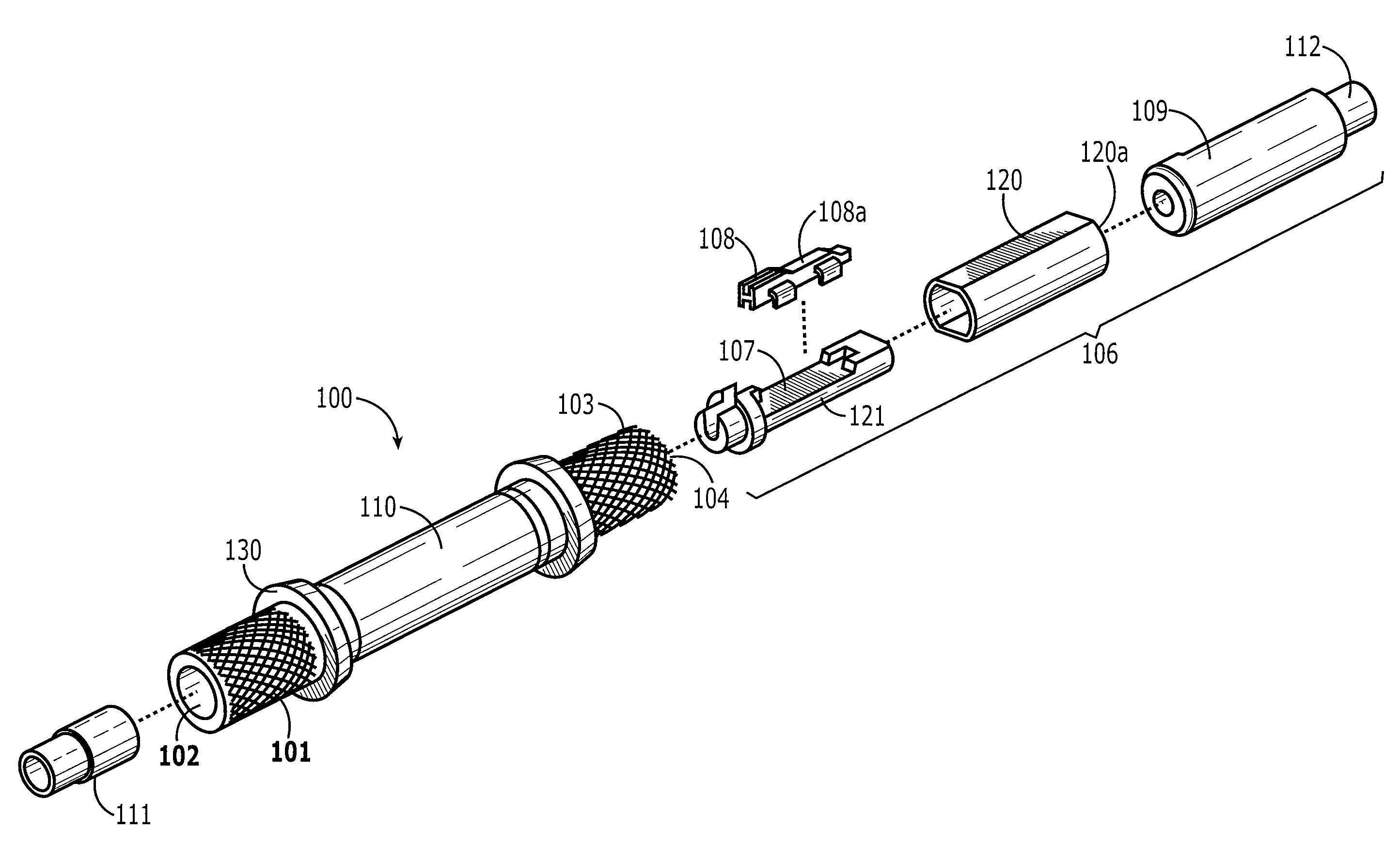
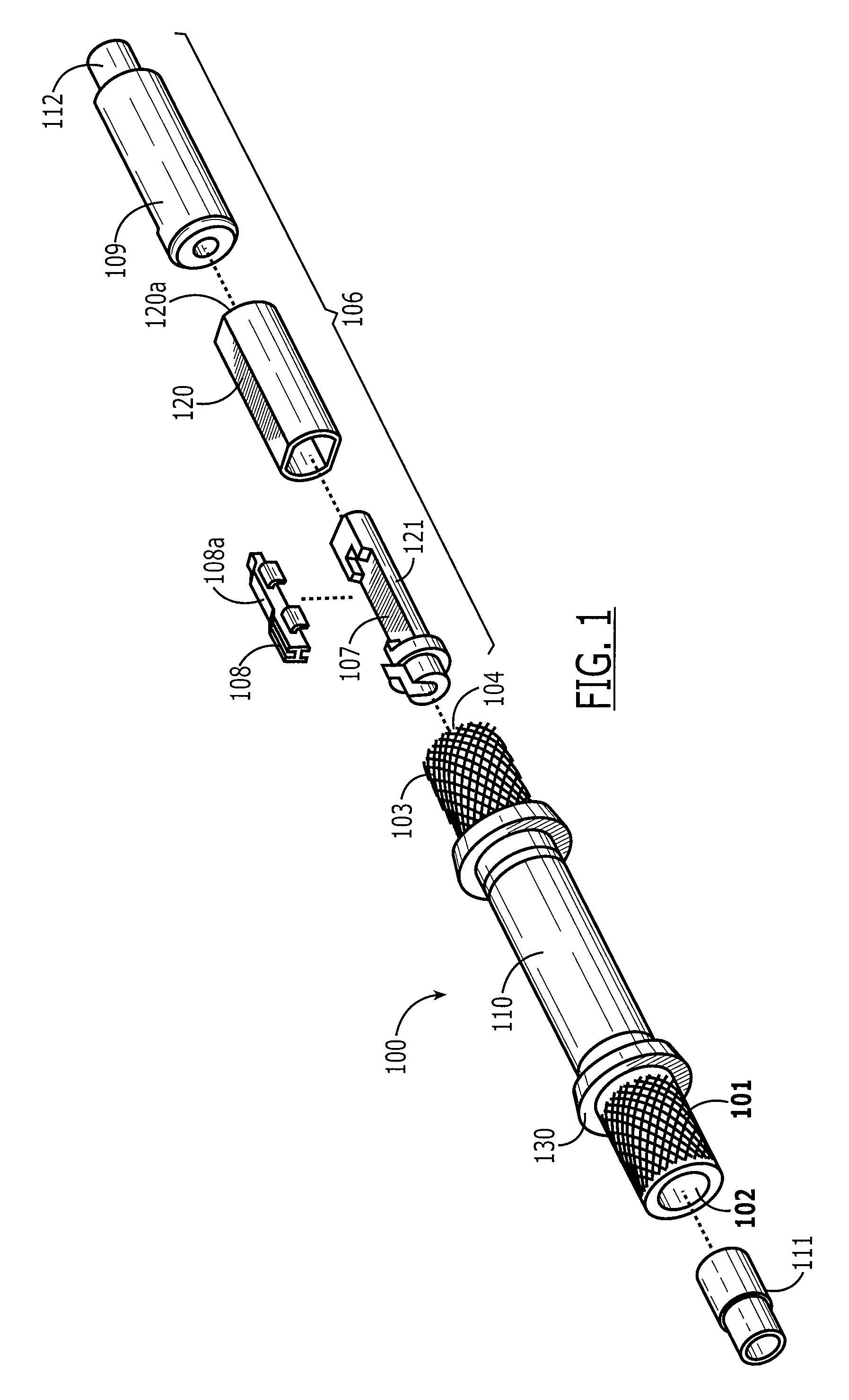
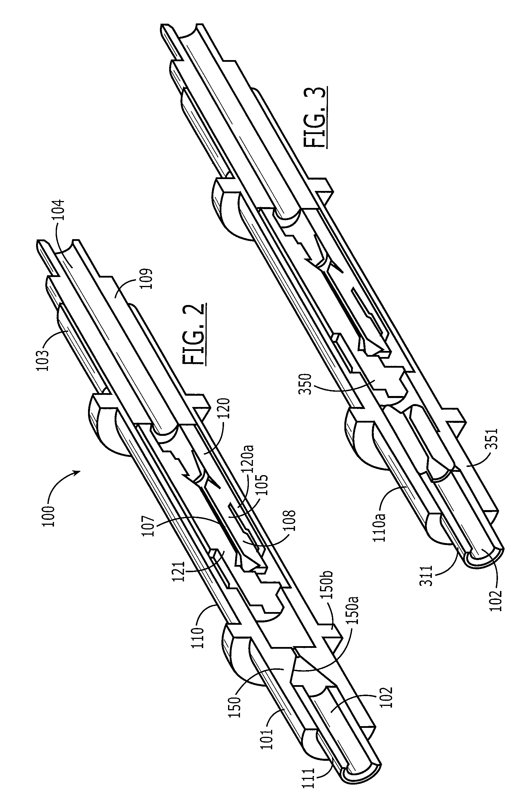
[0032]Referring to FIG. 1, an embodiment of the splice 100 of the present invention is shown. The splice comprises an elongated housing 110 having first end 101 with a first opening 102, a second end 103 with a second opening 104, and a central cavity 105. The housing is essentially seamless between the first and second ends. Disposed in the central cavity 105 is a claming mechanism 106. The clamping mechanism 106 defines a platform 121 having fiber-receiving channel 107 open to both the first and second openings 102, 104, a first member 108 adjacent to the fiber-receiving channel, and a second member 120 adjacent the first member 108. The first and second members have first and second cam surface 108a, 120a which cooperate such that, when one of either the first or second member is move axially toward the first end 101, the first member 108 moves toward the fiber-receiving channel. The clamping mechanism 106 also comprises an actuator 109 to move either the first or second member 1...
PUM
 Abstract
Description
Claims
Application Information