Air compressor having stable configuration

a stable configuration and air compressor technology, applied in the direction of positive displacement liquid engines, liquid fuel engines, piston pumps, etc., can solve the problems of poor air compressor use, poor air compressor use effect,

Inactive Publication Date: 2008-12-09
CHOU WEN SAN
View PDF13 Cites 96 Cited by
  • Summary
  • Abstract
  • Description
  • Claims
  • Application Information

AI Technical Summary

Benefits of technology

[0012]The primary objective of the present invention is to provide an air compressor including a stable configuration for stably supporting rotatable members on the supporting base, and for allowing the driving motor to be selectively supported on or attached onto a supporting base at different positions.
[0013]The other objective of the present invention is to provide an air compressor including a stable and solid supporting base to which the cylinder housing and the driving motor may be solidly attached, and to allow the cylinder housing and the driving motor to be stably and smoothly coupled together.
[0017]A spring-biased check valve may further be provided and disposed in the outlet tube and engaged with the valve seat, to limit the pressurized air to flow from the chamber of the cylinder housing into the bore of the outlet tube only, and to prevent the pressurized air from flowing backwardly from the bore of the outlet tube into the chamber of the cylinder housing.

Problems solved by technology

However, the cylinder housing is required to be attached onto the supporting base, and the motors are also required to be attached onto the supporting base selectively, such that the coupling between the motors and the cylinder housing may have a good chance to become loose, and such that the motor may have a good chance to swing or vibrate relative to the supporting base.
Furthermore, the typical air compressors may not be used to easily couple to various kinds of facilities that require pressurized air supplied thereto.

Method used


Image

  • Air compressor having stable configuration
  • Air compressor having stable configuration
  • Air compressor having stable configuration

Examples


Embodiment Construction

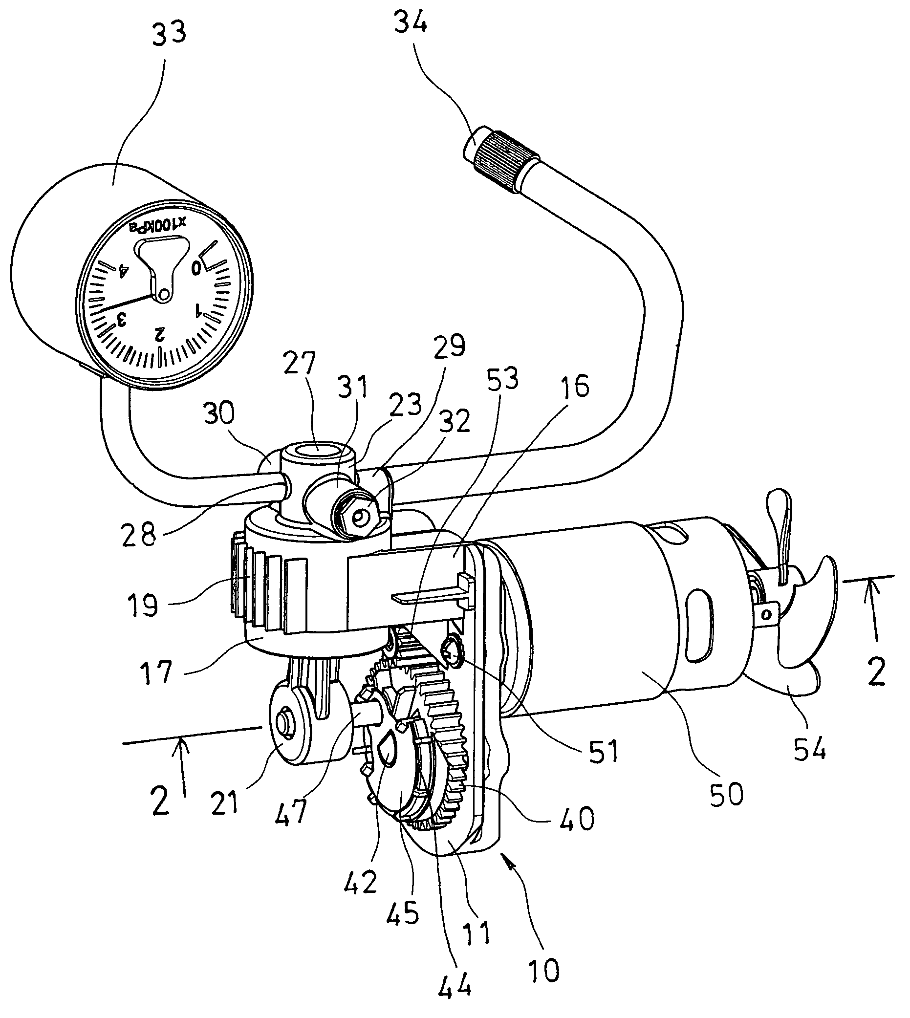
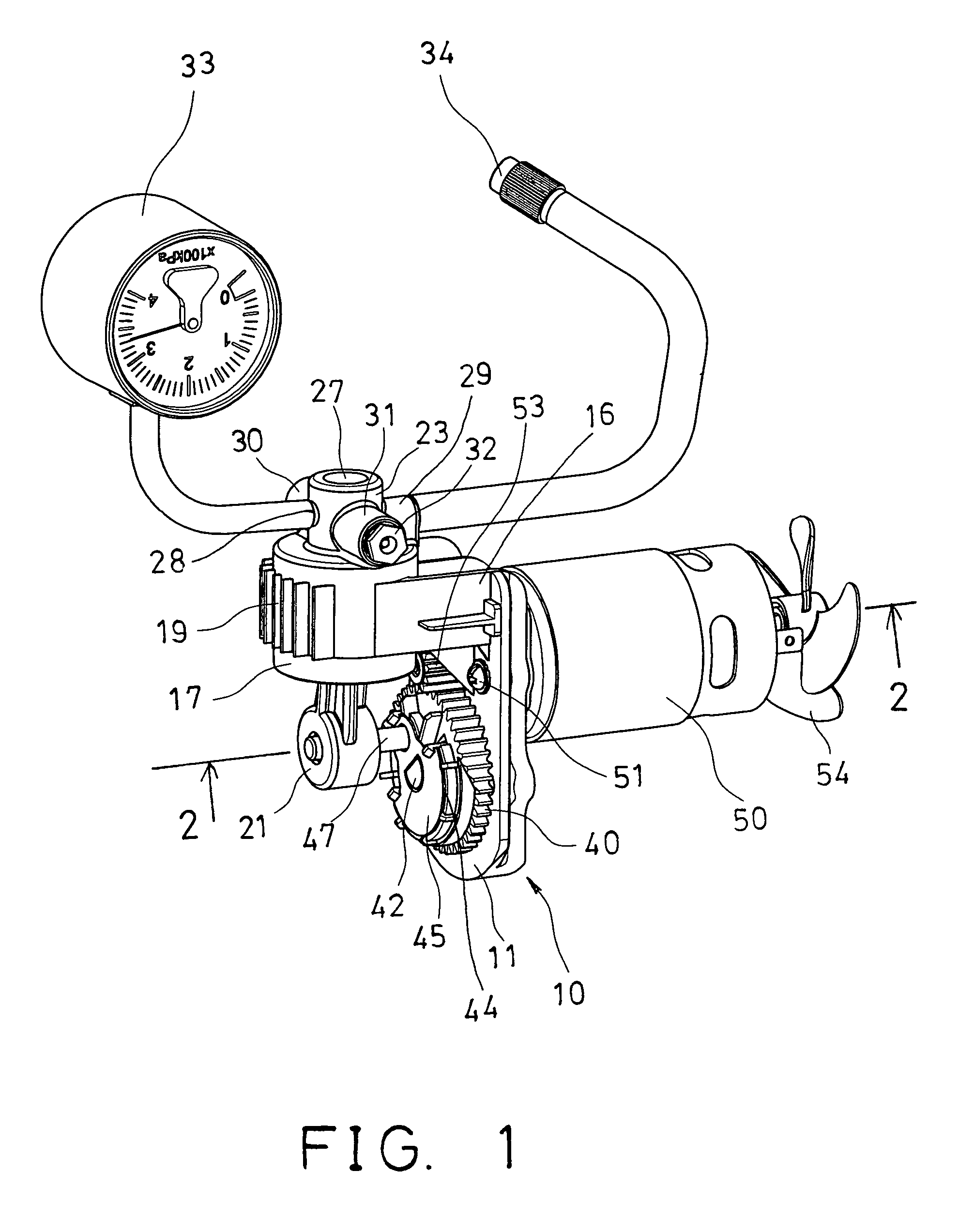
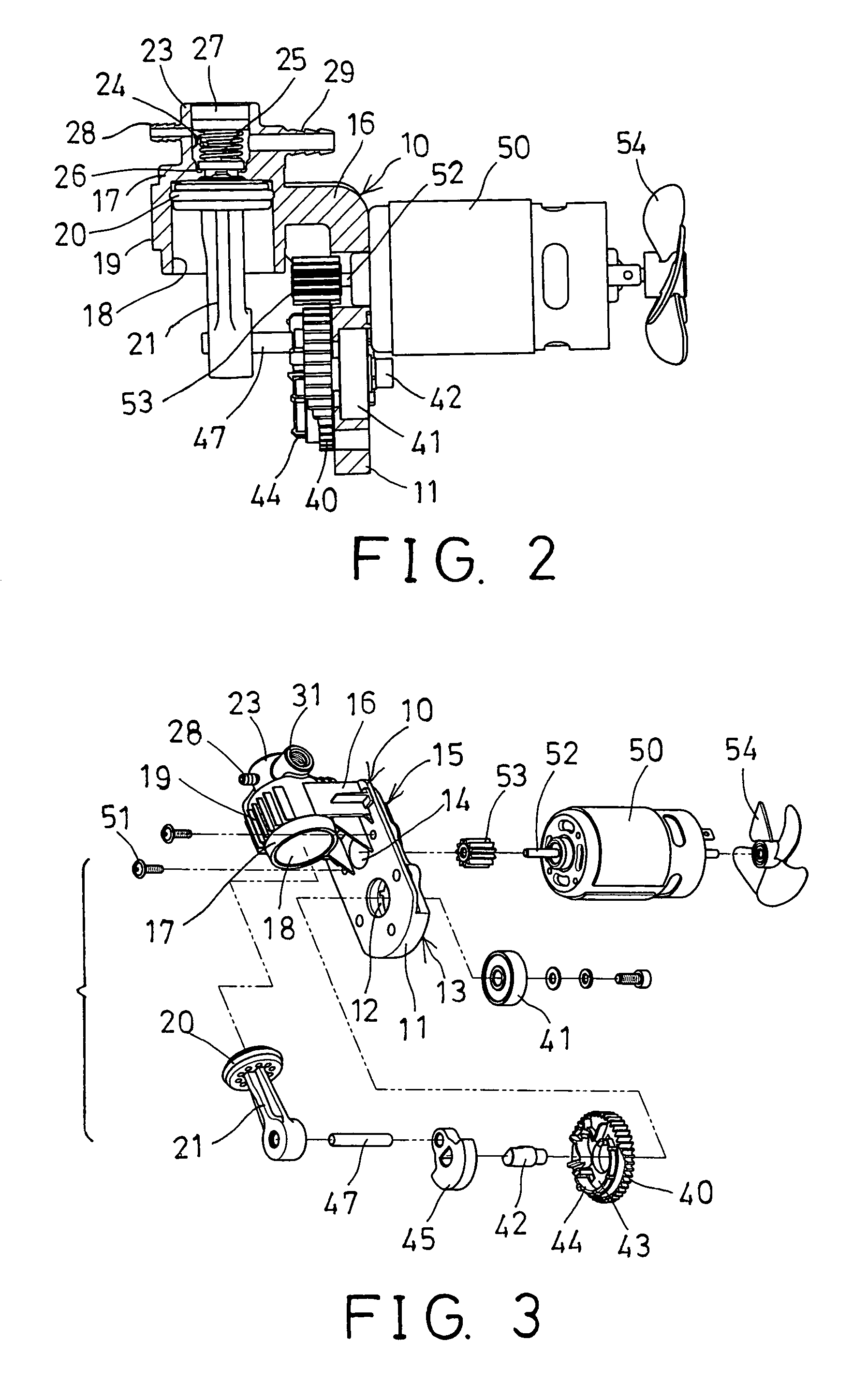
[0029]Referring to the drawings, and initially to FIGS. 1-5, an air compressor in accordance with the present invention comprises a supporting base 10 including a plate 11 having an opening 12 formed in a lower portion 13 thereof, and having an orifice 14 formed in an upper portion 15 thereof, and having an arm 16 laterally extended from the upper portion 15 thereof, and a cylinder housing 17 provided on or extended from the arm 16 and preferably formed integral with the arm 16 and the plate 11, best shown in FIGS. 2 and 7.

[0030]The cylinder housing 17 includes a chamber 18 formed therein (FIGS. 2-3, and 7-8), for slidably receiving a piston 20 therein, and includes one or more fins 19 extended laterally or radially outwardly therefrom, for such as heat dissipating purposes. The piston 20 is slidably received in the chamber 18 of the cylinder housing 17, and includes an extension or piston rod 21 extended therefrom, for allowing the piston 20 to slide in reciprocating action in the ...


PUM


Abstract

An air compressor includes a supporting base having an arm extended from a plate, and a cylinder housing formed integral with the arm and the plate and having an outlet tube. The cylinder housing includes three or more ducts extended outwardly from the outlet tube and communicating with the outlet tube, for attaching a pressure gauge, a nozzle or other devices. A piston is slidably received in the cylinder housing. A motor is attached to the plate, and includes a spindle extendible through either the lower or the upper portion of the plate, and coupled to the piston with an eccentric member, to move the piston to the cylinder housing in a reciprocating action, in order to generate pressurized air.

Description

[0001]The present invention is a continuous-in-part of U.S patent application Ser. No. 10 / 216,590, filed 12 Aug. 2002 now U.S. Pat No. 6,846,162, allowed.BACKGROUND OF THE INVENTION[0002]1. Field of the Invention[0003]The present invention relates to an air compressor, and more particularly to an air compressor having a stable configuration for stably supporting rotatable members, and for allowing a driving motor to be supported on or attached onto a supporting base at different positions, and for allowing the driving motor to be stably coupled to the cylinder housing with a solid supporting base.[0004]2. Description of the Prior Art[0005]Typical air compressors comprise a cylinder attached or secured to a base and having a piston slidably disposed therein, and a motor secured to the base and coupled to the piston of the cylinder for actuating or driving the piston of the cylinder in reciprocating action.[0006]The applicant has developed various kinds of typical air compressors, suc...

Claims


Application Information

Patent Timeline
Patent Type & Authority Patents(United States)
IPC IPC(8): F04B17/00F04B35/04F04B39/10F04B53/12F04B39/12F04B49/03
CPCF04B35/04F04B39/122F04B39/125F04B49/03
Inventor CHOU, WEN SAN
Owner CHOU WEN SAN
Why Eureka
Try Eureka