
Circuit board fixing structure

a technology of fixing structure and circuit board, which is applied in the direction of electrical apparatus construction details, coupling device connections, electrical apparatus casings/cabinets/drawers, etc., can solve the problems of circuit board damage by coupling members, signal interference with circuit boards, and difficulty in assembly and implementation, and achieves tight fixing

Inactive Publication Date: 2008-12-09
HON HAI PRECISION IND CO LTD
View PDF14 Cites 10 Cited by
  • Summary
  • Abstract
  • Description
  • Claims
  • Application Information

AI Technical Summary

Benefits of technology

Enables easy, tool-free assembly and secure fixation of the circuit board, preventing damage and reducing component costs while ensuring reliable attachment.

Problems solved by technology

To fix the above circuit board to the housing of the electronic device needs a screwdriver or a similar tool to screw the coupling members, which is rather troublesome and time-consuming to implement.
If a force for screwing the coupling members is not proper, the circuit board may be damaged by the coupling members.
Moreover, since the coupling members are often made of metallic material having electrical conductivity, a signal interference is existed with the circuit board.
When the circuit board or some component of the electronic device has some blemish, it is difficult to remove the blemished member and the whole circuit board is broken and useless.
However, too many components and too many steps increase the cost of the product.
Furthermore, the stud of this circuit board fixing structure maybe fall off from the pillar, and as a result, a fixing effect can't be achieved

Method used


Image

  • Circuit board fixing structure
  • Circuit board fixing structure
  • Circuit board fixing structure

Examples


Embodiment Construction

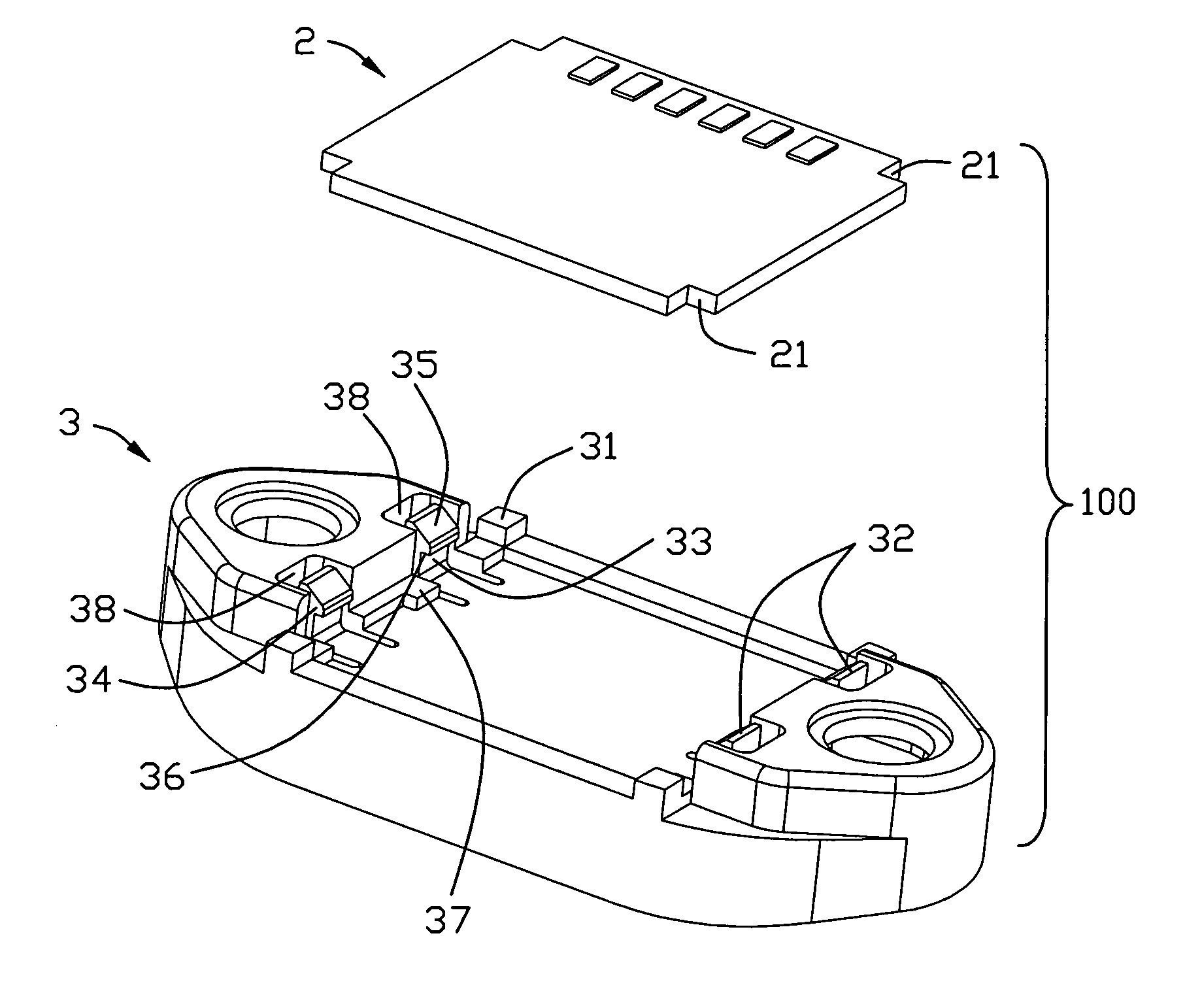
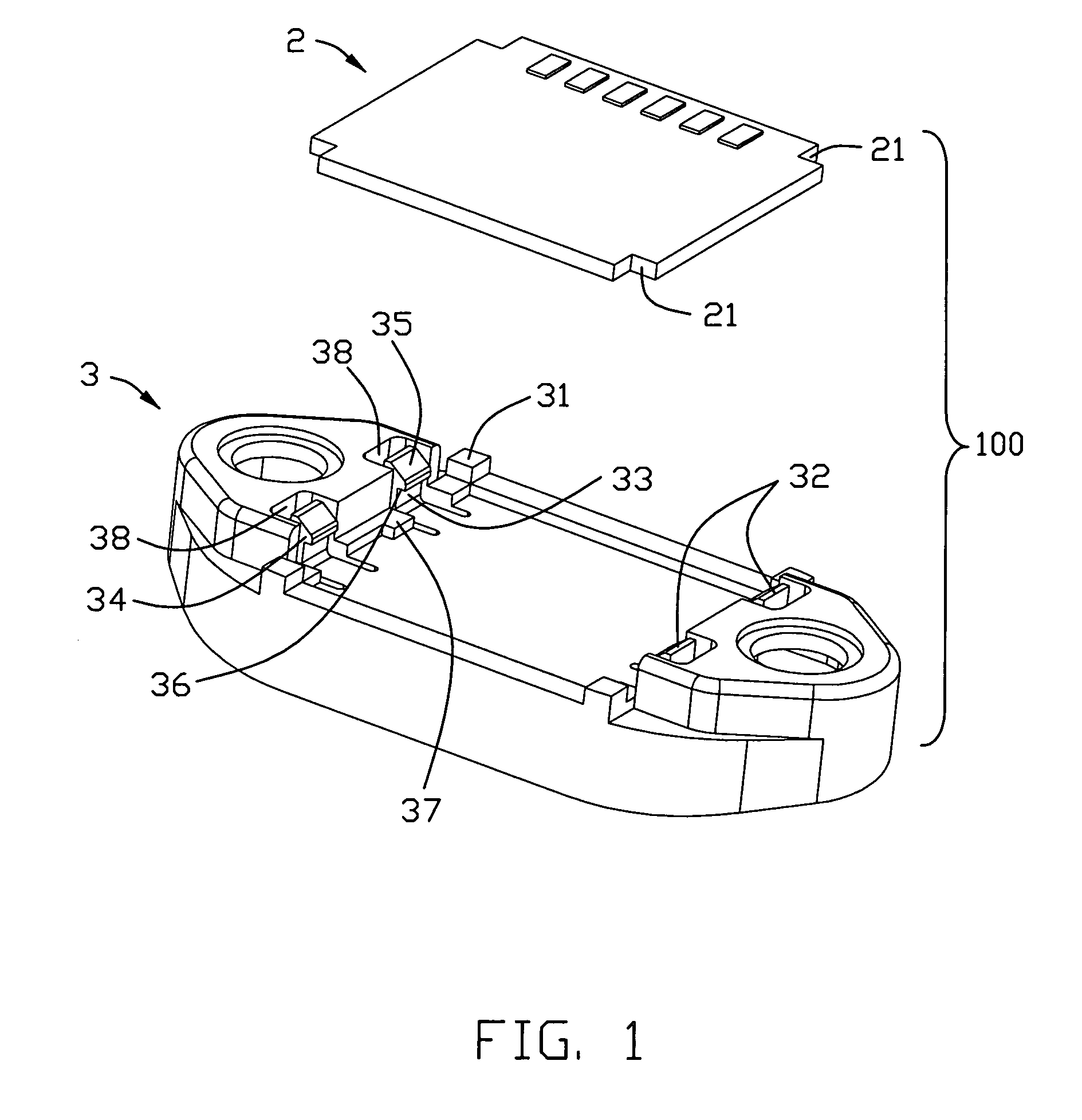
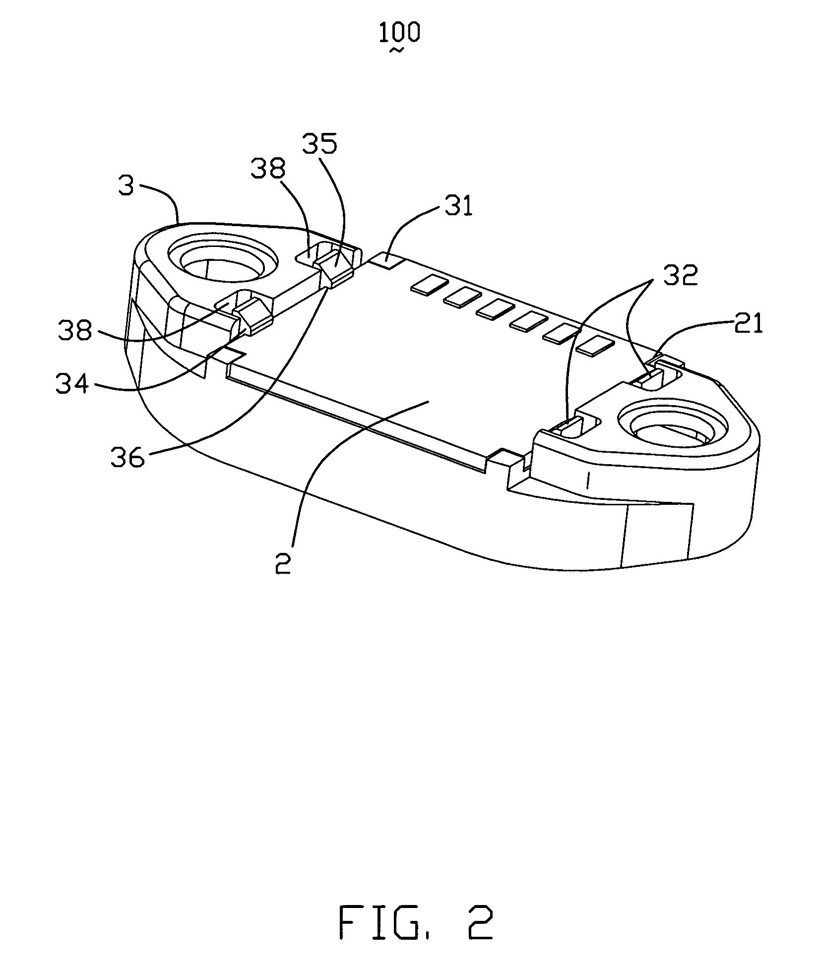
[0014]Referring to FIGS. 1 and 2, an embodiment is shown. A circuit board fixing structure 100 comprises a circuit board 2 and a base 3 on which the circuit board 2 is mounted. The circuit board 2 is approximately shaped as a quadrangle taken from a top view, but the four angles thereof recess to be four cutouts 21. The base 3 comprises four blocks 31 corresponding to the four cutouts 21 of the circuit board 2 and two pairs of elastic claws 32 locating at two opposite sides and facing to each other. The blocks 31 are used for limiting a movement of the circuit board 2 in a horizontal direction and the elastic claws 32 are used for limiting a movement of the circuit board 2 in a vertical direction. Each elastic claw 32, extending from an upper surface (not labeled) of the base 3, comprises a supporting bar 33 and a fastening portion 34. The supporting bar 33 is flexible and can endure a small deflection. The fastening portion 34, extending from a distal end of the supporting bar 33, ...


PUM


Abstract

A circuit board fixing structure (100) includes a base (3) and a circuit board (2). The base has a plurality of elastic claws (32) and the elastic claws vertically extend from the base. Each elastic claw includes a fastening portion (34), which forms a fastening surface (36) facing to a top surface of the base. The circuit board is encircled by the elastic claws and an upper surface of the circuit board confronts the fastening surface of the fastening portion.

Description

BACKGROUND OF THE INVENTION[0001]1. Field of the Invention[0002]The present invention relates generally to circuit board fixing structures, and more particularly to a fixing structure for a circuit board of an electronic device.[0003]2. Description of Related Arts[0004]As the technology advances, electronic devices such as desktop computers, laptop computers and services have played an important role in daily life. Each electronic device is provided with a circuit board (or a motherboard) fixed to a housing of the electronic device. Various ways of fixing the circuit board to the electronic device are available and cause different effects on the circuit board.[0005]One of conventional methods is that a housing of an electronic device is formed with a plurality of carried pads thereon, wherein each of the carried pads has a blind hole. A circuit board has a plurality of openings corresponding to the blind holes of the carried pads and is placed on the carried pads. The circuit board ...

Claims


Application Information

Patent Timeline
Patent Type & Authority Patents(United States)
IPC IPC(8): H01R13/62
CPCH05K7/1417
Inventor KUO, PETERDU, BING
Owner HON HAI PRECISION IND CO LTD
Learn More