Forearm and wrist exercise device

a wrist and wrist technology, applied in gymnastics, frictional force resistors, clubs, etc., can solve the problems of increasing the effort required to rotate the extension shaft, and increasing the effort required to rotate the handle rod. , to achieve the effect of increasing the force against the driver wheel, increasing the effort required to rotate the handle rod, and building muscle mass

Inactive Publication Date: 2008-12-09
PYRAMAX BANK FSB
View PDF7 Cites 4 Cited by
  • Summary
  • Abstract
  • Description
  • Claims
  • Application Information

AI Technical Summary

Benefits of technology

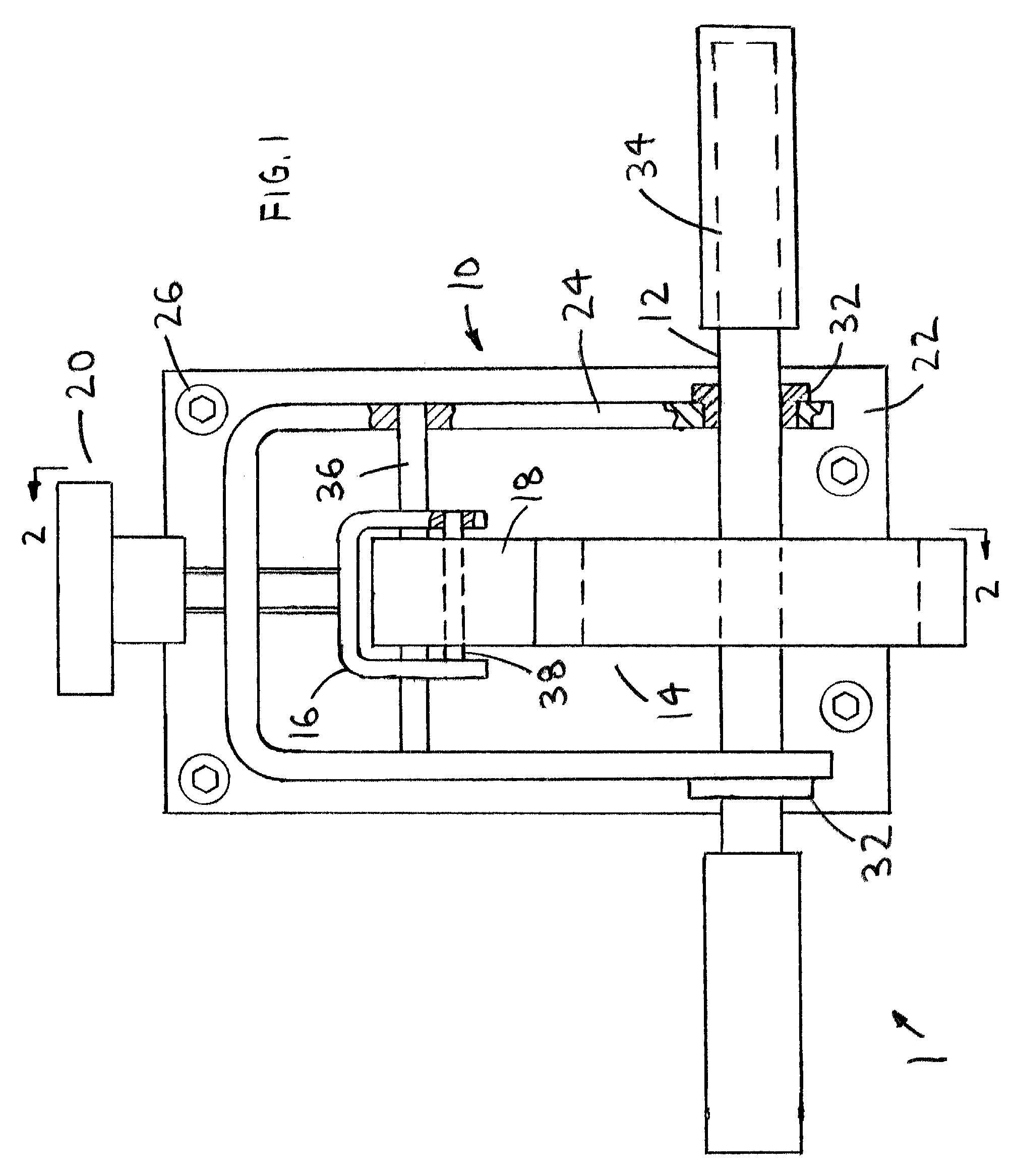
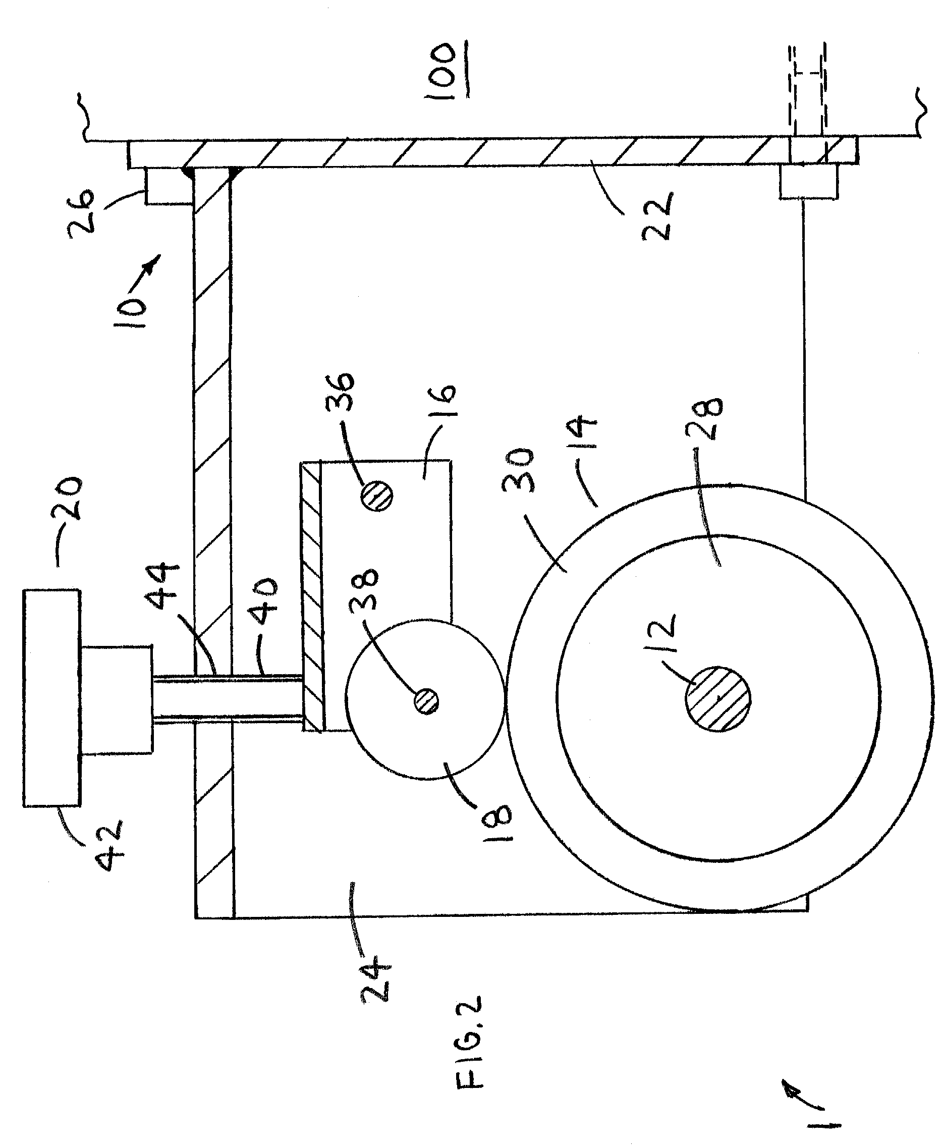
[0007]The present invention provides a forearm and wrist exercise device, which builds muscle mass by rotation of a pair of handles. The forearm and wrist exercise device (exercise device) preferably includes a base frame, a handle rod, a driver wheel, a driven yoke, a driven wheel and an adjustable tensioner. The base frame is attached to a stationary object, such as a wall. The driver wheel is attached to the handle rod and the handle rod is pivotally retained by the base frame. One end of the driven yoke is pivotally retained by the base frame and the driven wheel is pivotally retained in the other end. The driven wheel is forced against the driver wheel with the adjustable tensioner. Increasing the force against the driver wheel with the adjustable tensioner, increases the effort required to rotate the handle rod.
[0008]A second embodiment of the exercise device preferably includes a base frame, a handle rod, a driver wheel, a tension belt and an adjustable tensioner. The base frame is attached to a stationary object, such as a wall. The driver wheel is attached to the handle rod and the handle rod is pivotally retained by the base frame. The tension belt is wrapped around the driver wheel. The adjustable tensioner is retained in a top of the base frame. A first end of the tension belt is attached to the adjustable tensioner. One end of an extension spring is attached to a second end of the tension belt and the other end is attached to the base frame. Tightening the tension belt against the driver wheel with the adjustable tensioner increases the effort required to rotate the handle rod.
[0009]A third embodiment of the exercise device preferably includes a base frame, a hydraulic pump, a hydraulic flow valve and a pair of extension shafts. The base frame is attached to a stationary object, such as a wall. The hydraulic pump is attached to the base frame. The hydraulic pump includes a drive shaft, which extends from opposing sides thereof. A single extension shaft is attached to each end of the drive shaft with a shaft coupler or the like. The hydraulic pump also includes a hydraulic oil input and a hydraulic oil output. A first hydraulic line is connected between one inlet of the hydraulic flow valve and the hydraulic oil input and a second hydraulic line is connected between the other inlet of the hydraulic flow valve and the hydraulic oil output. Decreasing the flow area in the hydraulic flow valve, increases the effort required to rotate the pair of extension shafts.
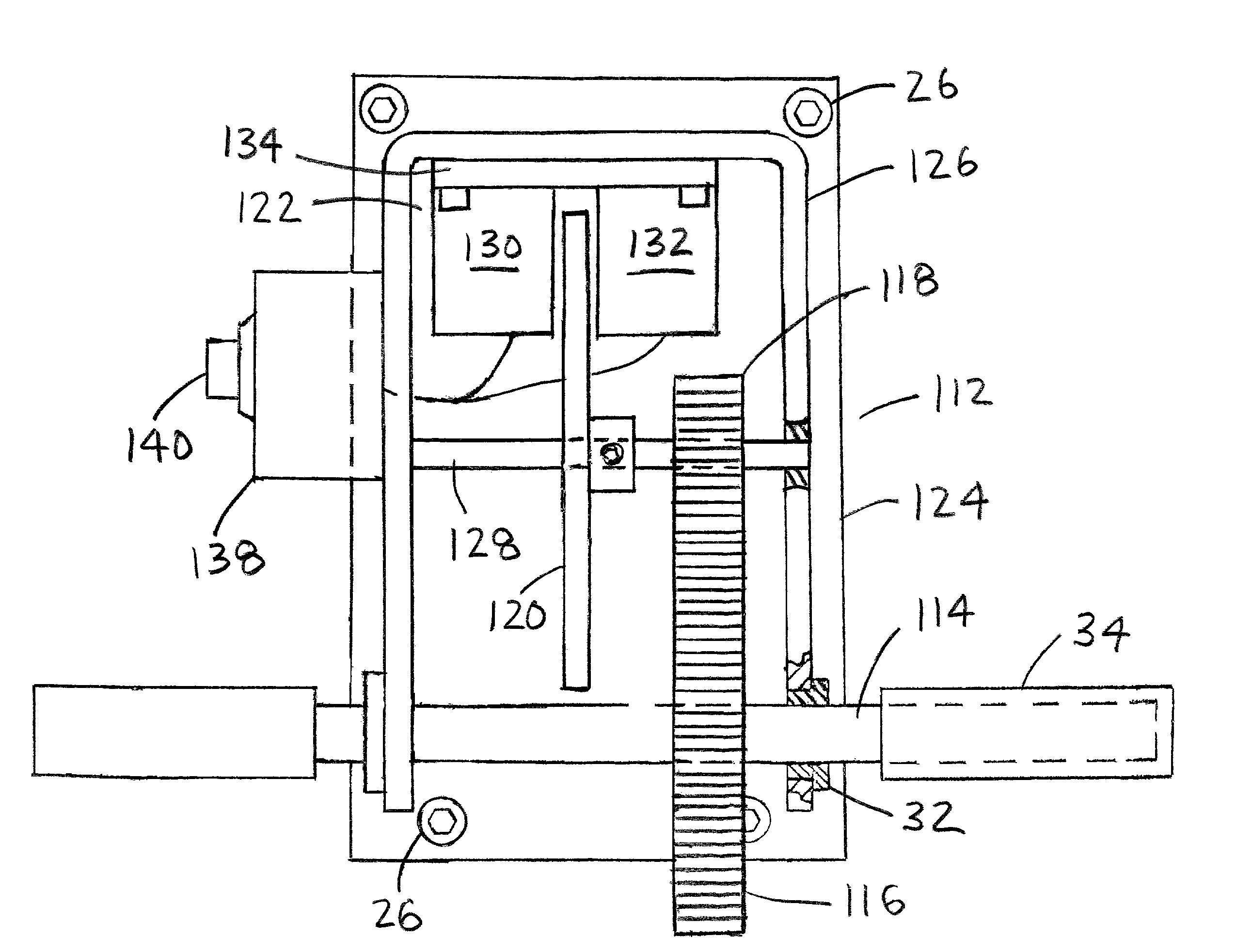
[0010]A fourth embodiment of the exercise device preferably includes a base frame, a handle rod, a driver gear, a driven gear, a flywheel and an electromagnet. The base frame is attached to a stationary object, such as a wall. The driver gear is attached to the handle rod. The handle rod is pivotally retained by the base frame. The driven gear and flywheel are retained on a driven rod. The driven rod is rotatably retained by the base frame. The electromagnet includes a first magnet, a second magnet and a mounting plate. The first magnet is attached to the mounting plate and the second magnet is attached to the mounting plate, adjacent the first magnet, such that a gap is created between the first and second magnets to receive a thickness of the flywheel. The mounting plate is attached to the base frame. A current control box is used to vary the electrical current supplied to the first and second magnets. Increasing the electrical current flow through the first and second magnets, increases the effort required to rotate the handle rod.
[0011]Accordingly, it is an object of the present invention to provide an exercise device with adjustable rotating resistance to provide a smooth forearm and wrist exercise.

Problems solved by technology

Increasing the force against the driver wheel with the adjustable tensioner, increases the effort required to rotate the handle rod.
Tightening the tension belt against the driver wheel with the adjustable tensioner increases the effort required to rotate the handle rod.
Decreasing the flow area in the hydraulic flow valve, increases the effort required to rotate the pair of extension shafts.
Increasing the electrical current flow through the first and second magnets, increases the effort required to rotate the handle rod.

Method used


Image

  • Forearm and wrist exercise device
  • Forearm and wrist exercise device
  • Forearm and wrist exercise device

Examples


second embodiment

[0023]With reference to FIGS. 3-4, the exercise device 2 preferably includes the base frame 10, the handle rod 14, a driver wheel 46, a tension belt 48 and the adjustable tensioner 20. The mounting plate 22 is attached to a stationary object, such as the wall 100 with fasteners 26 or the like. The driver wheel 46 includes a belt groove 50 formed in a perimeter thereof. The belt groove 50 is sized to receive a width of the tension belt 48. The belt groove 50 prevents the tension belt 48 from slipping off the driver wheel 46. A first belt rod 52 is inserted into holes formed through opposing sides of the wheel yoke 24. A second belt rod 54 is inserted into holes formed through opposing sides of the wheel yoke 24. The first and second belt rods ensure that the tension belt 48 makes maximum contact with the driver wheel 46. A first clip 56 is preferably retained on a first end of the tension belt 48 by folding over the first end of the tension belt 48 and attaching thereof to itself. A ...

third embodiment

[0026]With reference to FIGS. 5-6, the exercise device 2 includes a base frame 74, a hydraulic pump 76, a hydraulic flow valve 78 and a pair of extension shafts 80. The base frame 74 includes a mounting plate 82 and a pump yoke 84. An end of the pump yoke 84 is attached to the mounting plate 82 with any suitable process. The mounting plate 82 is attached to a stationary object, such as the wall 100 with fasteners 26 or the like. The hydraulic pump 76 is preferably mounted to a spacer plate 86 with at least two fasteners 88. Two support feet 90 preferably extend from each side of the spacer plate 86. The two support feet 90 are attached to a side of the pump yoke 84 with at least two fasteners 92.

[0027]The hydraulic pump 76 includes a drive shaft 94, which extends from opposing sides thereof. A single extension shaft 80 is attached to each end of the drive shaft 94 with a shaft coupler 96 or the like. The pair of bearings 32 are preferably inserted into opposing sides of the pump yok...


PUM


Abstract

A forearm and wrist exercise device includes a base frame, a handle rod, a driver wheel, a driven yoke, a driven wheel and an adjustable tensioner. The base frame is attached to a stationary object, such as a wall. The handle rod extends from the driver wheel and the handle rod is pivotally retained by the base frame. The driven wheel is forced against the driver wheel. A second embodiment of the forearm and wrist exercise device includes a base frame, a handle rod, a driver wheel, a tension belt and an adjustable tensioner. A third embodiment of the forearm and wrist exercise device includes a base frame, a hydraulic pump, a hydraulic flow valve and a pair of extension shafts. A fourth embodiment of the forearm and wrist exercise device includes a base frame, a handle rod, a driver gear, a driven gear, a flywheel and an electromagnet.

Description

CROSS-REFERENCES TO RELATED APPLICATIONS[0001]This is a continuation-in-part patent application taking priority from nonprovisional application Ser. No. 10 / 826,714 filed on Apr. 16, 2004 now U.S. Pat. No. 7,351,186.BACKGROUND OF THE INVENTION[0002]1. Field of the Invention[0003]The present invention relates generally to exercise devices and more specifically to a forearm and wrist exercise device, which builds muscle mass in forearms, wrists and hands.[0004]2. Discussion of the Prior Art[0005]There are numerous devices, which may be used to strengthen the muscles in forearms, wrists and hands. U.S. Pat. No. 4,239,208 to Walls discloses a wrist and forearm conditioner and exerciser. The Walls patent includes a handle that becomes tensioned as thereof is rotated. U.S. Pat. No. 5,634,871 to Froelich, Sr. et al. discloses an adjustable rotating resistance exerciser. The Froelich, Sr. et al. patent includes a handle those rotating resistance may be adjusted by rotating an adjustment knob...

Claims


Application Information

Patent Timeline
IPC IPC(8): A63B21/22A63B15/02
CPCA63B21/0081A63B21/0125A63B21/018A63B21/22A63B23/12A63B23/14A63B23/16A63B21/00069A63B21/008A63B23/03525A63B21/4035
Inventor HERMAN, RICHARD L.SMITH, GORDON H.
Owner PYRAMAX BANK FSB
Why Eureka
Try Eureka