
Device and method for assisting in the implantation of a prosthetic valve

a prosthetic valve and implantation device technology, applied in the field of medical devices for implantation, can solve the problems of recoil after, difficult or impossible to advance the stented valve through the introducer sheath, and limited size of the introducer sheath, so as to facilitate the percutaneous delivery of medical devices, reduce the diameter of the crimped prosthetic valve, and enhance the pushability

Active Publication Date: 2008-12-09
EDWARDS LIFESCI PVT
View PDF109 Cites 639 Cited by
  • Summary
  • Abstract
  • Description
  • Claims
  • Application Information

AI Technical Summary

Benefits of technology

[0008]Embodiments of the present invention provide devices and methods for delivering a medical device into a patient's vasculature. Preferred embodiments facilitate percutaneous delivery of a medical device via an introducer sheath. More particularly, embodiments of the present invention provide devices and methods for facilitating advancement of a stented prosthetic valve through an introducer sheath by enhancing pushabilty and / or reducing the diameter of the crimped prosthetic valve.
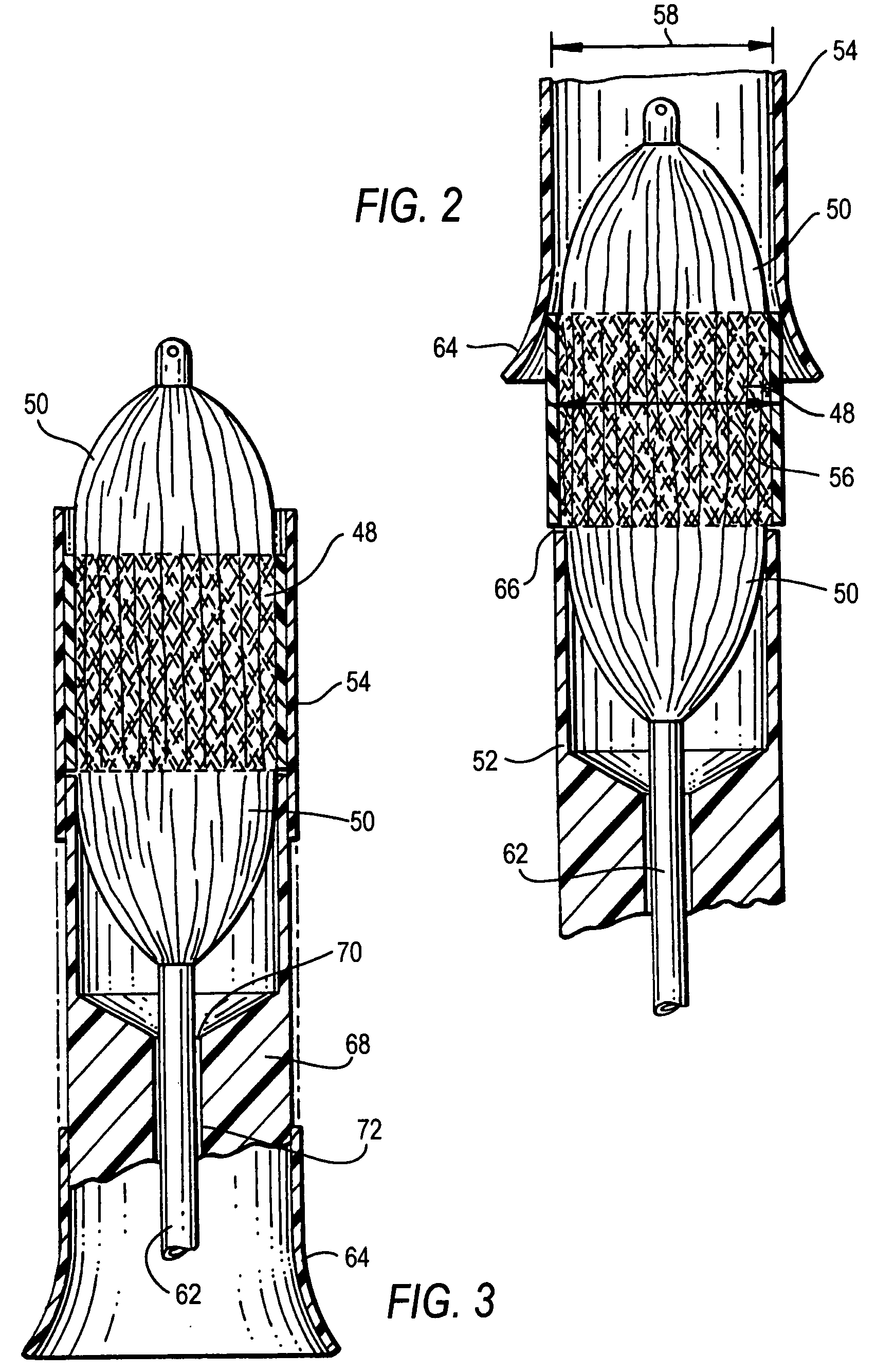
[0009]In one preferred embodiment, a system for percutaneously introducing a prosthetic valve into a patient's vasculature comprises a balloon dilatation catheter having an elongate shaft and a dilatation balloon disposed along a distal end portion. A prosthetic valve is formed with an expandable stent member and a valvular structure and the prosthetic valve is positioned coaxially to the dilatation balloon. A pusher member is formed with a longitudinal slot for accepting the elongate shaft, the pusher member having a distal end corresponding to a proximal end of the expandable stent for transferring longitudinal forces to the expandable stent from a location outside the patient's vasculature, the pusher member being slidable relative to the elongate shaft. In one variation, the longitudinal slot comprises at least one area that is wider than a remaining portion of the slot. In another variation, a cover member is positioned over a distal end of the dilatation balloon, the cover member having two or more substantially equally spaced openings arranged around the cover member. The dilatation balloon may expand through the openings as the dilatation balloon is inflated. In another variation, a cover member is positioned over a distal end of the dilatation balloon, the cover member comprising a multitude of substantially equally sized members that form a substantially conical shape before the balloon is inflated. To create a seal between the pusher member and the introducer sheath, a cooperating sealing member may be provided that can be advanced distally over the pusher member. To further assist in the advancement of the prosthetic valve, the pusher member may further comprise at least one internal support member.
[0010]In another preferred embodiment, a system for assisting in introduction and implantation in a body lumen of a crimped stent-mounted percutaneous valve assembly is provided wherein the valve assembly is carried on a delivery catheter comprising a shaft and stent expansion mechanism. The system includes a pusher member comprising a slotted tube that accepts the shaft, the distal end of the pusher member being sized for contact with a proximal end of the valve assembly. An introducer sheath is formed with a tapered opening configured to provide further crimping of the assembly when the valve assembly is longitudinally advanced through the tapered opening. A tapering is provided along a distal end of the valve assembly enabling the valve assembly to avoid catching on obstructions in the lumen. To increase the contact area between the distal end of the pusher member and the proximal end of the valve assembly, the slot in the pusher member may be relatively narrow along the distal end portion. A widening region may be provided along the pusher member proximal to the narrow portion for facilitating insertion of the catheter shaft into the slot. In yet another variation, the expansion mechanism may expand in such a fashion that the expansion mechanism contacts a portion of the body lumen, thereby anchoring the expansion mechanism and preventing longitudinal movement during deployment.

Problems solved by technology

Although stented valves may be crimped or compressed to a smaller diameter for delivery purposes, it has been found that some degree of recoil occurs after the crimping or compression process.
This is a particularly undesirable feature because the stented valve is typically advanced through an introducer sheath.
Furthermore, the size of the introducer sheath is limited by the size of the entry into a patient's blood vessel.
Therefore, due to recoil and other factors, when the size of the entry into the patient's blood vessel is small, it can be difficult or impossible to advance the stented valve through the introducer sheath.

Method used


Image

  • Device and method for assisting in the implantation of a prosthetic valve
  • Device and method for assisting in the implantation of a prosthetic valve
  • Device and method for assisting in the implantation of a prosthetic valve

Examples


Embodiment Construction

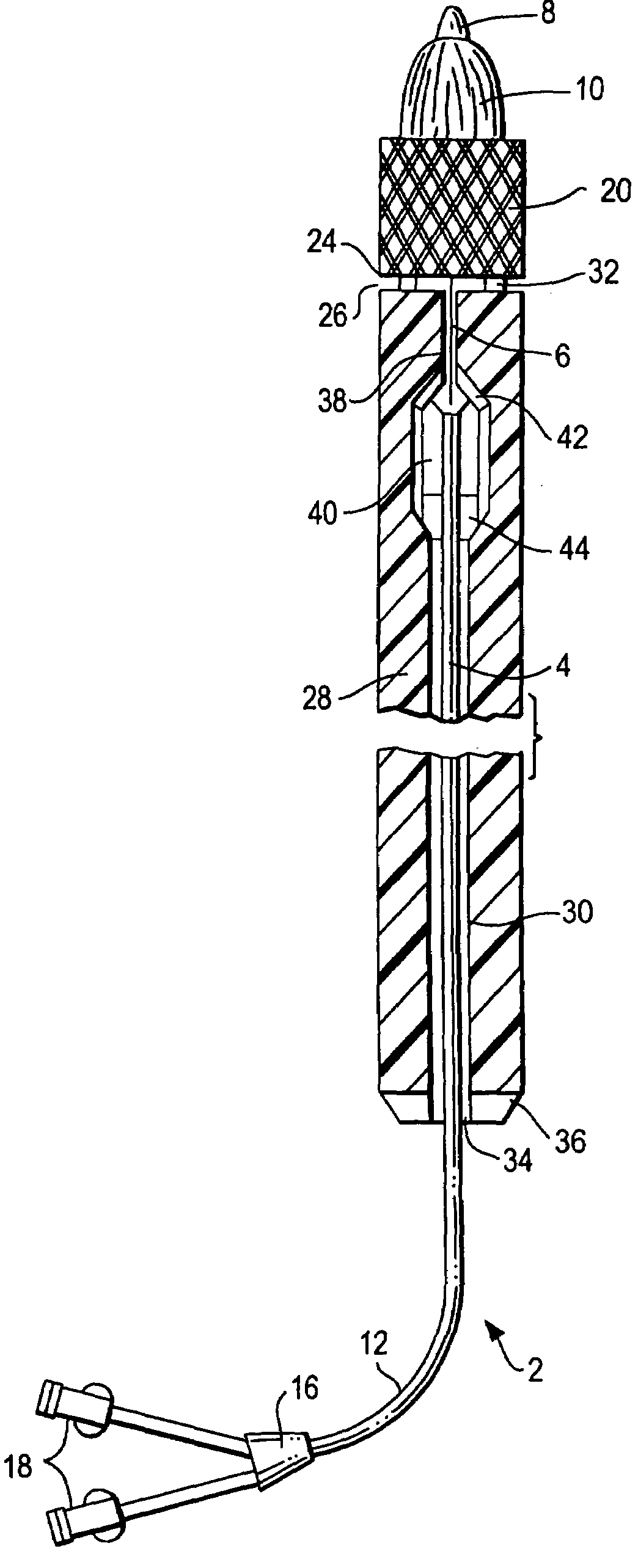
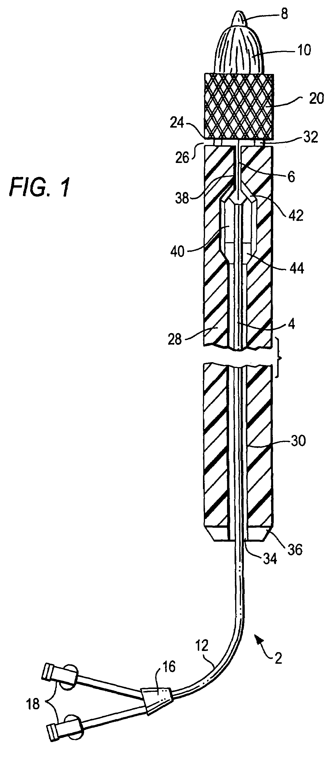
[0026]Preferred embodiments of the present invention provide devices and methods for facilitating advancement of a stented prosthetic valve through an introducer sheath to a treatment site. With reference now to the partial cross-sectional view of FIG. 1, for purposes of illustration, a balloon dilatation catheter 2 is shown. The balloon dilatation catheter 2 comprises a catheter shaft 4, which extends distally through a non-inflated dilatation balloon 6. The distal portion 8 of shaft 4 extends distally of the distal end 10 of dilatation balloon 6. Catheter shaft 4 has at least one lumen (not shown) capable of slidably receiving a guidewire (not shown).

[0027]The proximal end 12 of catheter 2 comprises a junction 16 in fluid communication with one or more manifolds 18 for entry of a guidewire, for example, or another device, substance, or fluid. For example, one manifold 18 may be in fluid communication with an inflation lumen (not shown) for dilatation balloon 6, and another manifol...


PUM


Abstract

A system for percutaneously introducing a prosthetic valve into a patient's vasculature comprises a balloon dilatation catheter, a prosthetic valve mounted coaxial to the dilatation balloon, and a pusher member comprising a longitudinally extending tubular member encompassing the shaft of the catheter. The distal end of the pusher member preferably corresponds to the proximal end of the stent component of the prosthetic valve. The pusher member provides enhanced longitudinal pushability for facilitating advancement of the prosthetic valve to a treatment site. The system is well-suited for advancing a prosthetic valve or other medical device through an introducer sheath having a relatively small inner diameter. The introducer sheath may be formed with a tapered proximal end portion for receiving the prosthetic valve and for reducing a diameter of the prosthetic valve during advancement therethrough.

Description

RELATED APPLICATION[0001]The present application claims priority under 35 U.S.C. §119(e) to U.S. provisional application 60 / 584,903, filed Jun. 30, 2004.FIELD OF THE INVENTION[0002]The present invention relates to methods and devices for implanting medical devices in a human body. More particularly, the present invention relates to methods and devices for assistance in implanting a prosthetic valve in a patient's heart or other body duct.BACKGROUND OF THE INVENTION[0003]The implantation of prosthetic valves using percutaneous techniques is a relatively new field of medicine. While percutaneous implantation has yet to achieve widespread acceptance, there are several companies developing such procedures and products. In this field, it has been found that stented valves are particularly well-suited for percutaneous advancement to a treatment site. Stented valves can be divided basically into two groups: self-expanding stented valves and expandable, i.e., internally-expanded, stented va...

Claims


Application Information

Patent Timeline
Patent Type & Authority Patents(United States)
IPC IPC(8): A61F2/06
CPCA61F2/2433A61F2/2436A61F2/2418
Inventor SPENSER, BENJAMINBENICHOU, NETANELBASH, ASSAFTUBISHEVITZ, AMIT
Owner EDWARDS LIFESCI PVT
Learn More