Activation of carbon nanotubes for field emission applications

a carbon nanotube and field emission technology, applied in the field of field emitters, can solve the problems of difficult to achieve the high uniformity required for display applications, the cvd process is not a good way to grow cnts, and none of them can be processed on large areas uniformly, so as to improve the field emission properties of cnts, the effect of easy and low cost processing

Inactive Publication Date: 2008-12-09
APPLIED NANOTECH HLDG
View PDF23 Cites 10 Cited by
  • Summary
  • Abstract
  • Description
  • Claims
  • Application Information

AI Technical Summary

Benefits of technology

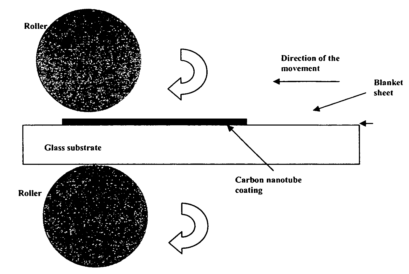
[0009]Unlike the adhesive tape activation process, the present invention does not remove significant amounts of the CNTs, but flattens and creates a new structure for the CNT layer. The blanket sheet used in this invention is non-adhesive, and therefore there is no organic residue remaining on the substrate. This method was compared with the taping process and much better field emission properties of the CNTs were achieved. This process has several advantages:

Problems solved by technology

But the CVD process is not a good way to grow CNTs over large areas because it is very difficult to achieve high uniformity required for display applications.
But none of them can be processed on large areas uniformly.
The organic residue on the substrate after the taping activation process may give off undesirable residual gases in the sealed glass display envelope during field emission operation.
Furthermore, it is difficult to uniformly activate the substrate over large areas.
All of these problems obviously obstruct the various field emission applications of CNTs.

Method used


Image

  • Activation of carbon nanotubes for field emission applications
  • Activation of carbon nanotubes for field emission applications
  • Activation of carbon nanotubes for field emission applications

Examples


Embodiment Construction

[0029]In the following description, numerous specific details are set forth to provide a thorough understanding of the present invention. However, it will be obvious to those skilled in the art that the present invention may be practiced without such specific details. In other instances, well-known circuits have been shown in block diagram form in order not to obscure the present invention in unnecessary detail. For the most part, details concerning timing considerations and the like have been omitted inasmuch as such details are not necessary to obtain a complete understanding of the present invention and are within the skills of persons of ordinary skill in the relevant art.

[0030]Refer now to the drawings wherein depicted elements are not necessarily shown to scale and wherein like or similar elements are designated by the same reference numeral through the several views.

1. Source of Carbon Nanotube and Alumina Powders

[0031]Used for creating samples for the present invention were ...


PUM

PropertyMeasurementUnit
temperatureaaaaaaaaaa
diameteraaaaaaaaaa
diameteraaaaaaaaaa

Abstract

Substantially enhanced field emission properties are achieved by using a process of covering a non-adhesive material (for example, paper, foam sheet, or roller) over the surface of the CNTs, pressing the material using a certain force, and removing the material.

Description

[0001]This application claims priority to U.S. Provisional Application Ser. No. 60 / 585,771. This application is a continuation-in-part of U.S. patent application Ser. No. 10 / 269,577, which claims benefit to U.S. Provisional Applications Nos. 60 / 343,642; 60 / 348,856; and 60 / 369,794, which are all hereby incorporated by reference herein.TECHNICAL FIELD[0002]The present invention relates in general to field emitters, and in particular, to field emitters utilizing carbon nanotubesBACKGROUND INFORMATION[0003]Carbon nanotubes (CNTs) are being investigated by a number of companies and institutions because of their unbelievable physical, chemical, electronical, and mechanical properties (Walt A. de Heer, “Nanotubes and the Pursuit of Applications,” MRS Bulletin 29(4), pp. 281-285 (2004)). They can be used as excellent cold electron sources for many applications such as displays, microwave sources, x-ray tubes, etc., because of their excellent field emission properties and chemical inertness ...

Claims


Application Information

Patent Timeline
Patent Type & Authority Patents(United States)
IPC IPC(8): H01L51/40H01J9/02H01L21/00
CPCB82Y10/00H01J1/304H01J9/025H01J31/127H01J2201/30469Y10S977/888Y10S977/857Y10S977/855Y10S977/858Y10S977/859B82Y40/00
Inventor MAO, DONGSHENGFINK, RICHARDYANIV, ZVI
Owner APPLIED NANOTECH HLDG
Why Eureka
Try Eureka