Eureka AIR delivers breakthrough ideas for toughest innovation challenges, trusted by R&D personnel around the world.

Linear motor and stage device using the linear motor

a technology of linear motors and stage devices, applied in the direction of electric/magnetic/electromagnetic heating, induction heating, dynamo-electric machines, etc., can solve the problems of increasing manufacturing costs, affecting the external environment of heat generated by coils, and not being able to insert panel-shaped heat pipes

Inactive Publication Date: 2008-12-09
SUMITOMO HEAVY IND LTD
View PDF24 Cites 3 Cited by
  • Summary
  • Abstract
  • Description
  • Claims
  • Application Information

AI Technical Summary

Benefits of technology

[0013]Accordingly, embodiments of the present invention may provide a novel and useful linear motor and stage device using the linear motor in which one or more of the problems described above are eliminated.
[0014]More specifically, the embodiments of the present invention can provide a linear motor and stage device using the linear motor whereby cooling efficiency of a coil is improved.
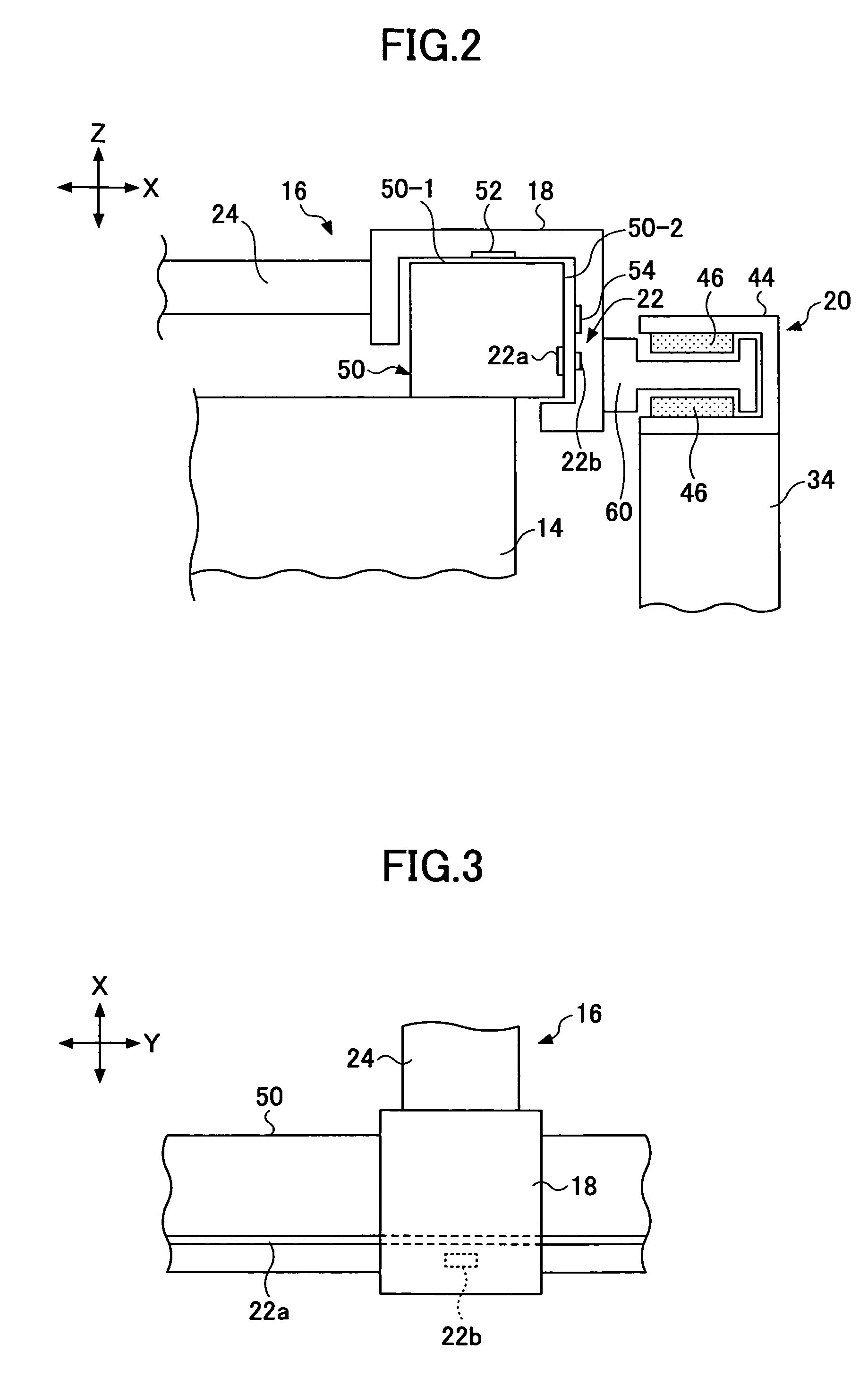
[0017]According to the above-mentioned linear motor, the coil cooling part includes the cooling panel having the heat conductive element, the heat conductive element transferring heat of the coil part to the outside; and the heat radiation part connected to the cooling panel, the heat radiation part being configured to radiate the heat transferred from the heat conductive element to the outside. Hence, heat of the coil part is efficiently radiated outside in a simple structure so that temperature of the coil part is prevented from being increased. As a result of this, it is possible to prevent decreasing a driving force. Even if neighboring coils are alternately overlapped, it is possible to sufficiently cool the coil part.
[0018]Therefore, in the above-mentioned stage device, even if the coil has a complex configuration in order to solve the lack of torque problem, it is possible to efficiently cool the coil part from a periphery of the coil part. Hence, it is possible to increase torque and realize minute high speed control so that it is possible to prevent decrease of a thrust force due to cooling of the coil part.

Problems solved by technology

In addition, heat generated from the coil influences the external environment.
Hence, while lack of torque is solved so that minute moving control is realized, it is not possible to insert the panel shape heat pipe in the gap between the coil lines bending in a crank shape.
Hence, the structure may be maximized and complex so that manufacturing cost may be increased.

Method used


Image

  • Linear motor and stage device using the linear motor
  • Linear motor and stage device using the linear motor
  • Linear motor and stage device using the linear motor

Examples


Embodiment Construction

[0034]A description will now be given, with reference to FIG. 1 through FIG. 14, of embodiments of the present invention.

First Example of the Present Invention

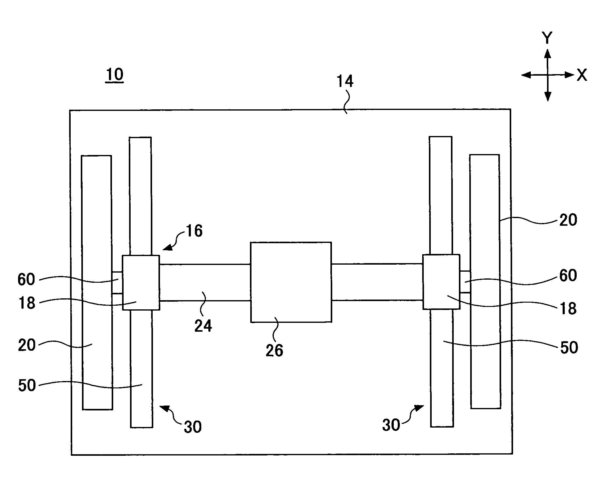
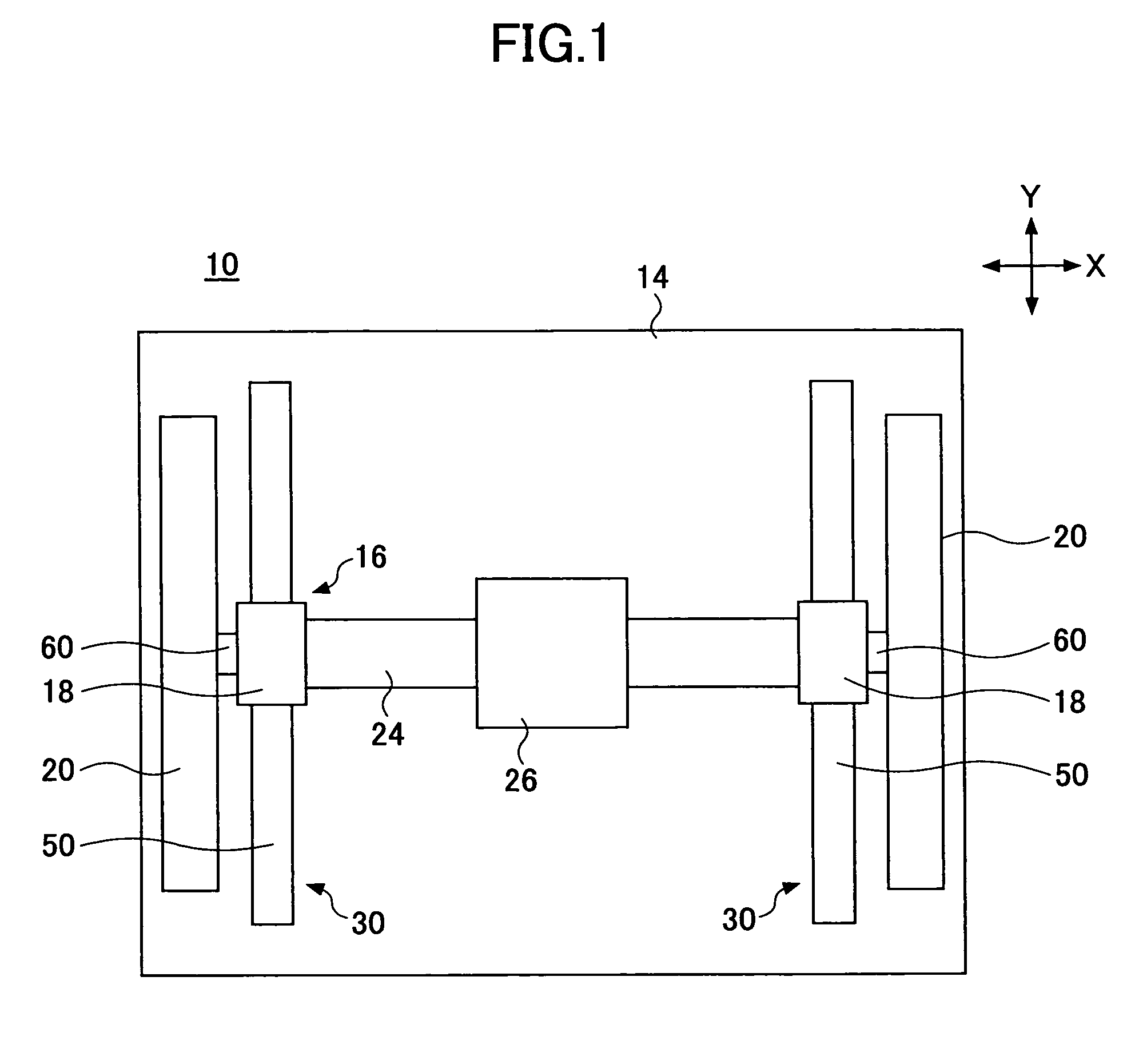
[0035]FIG. 1 is a plan view of a stage device where a linear motor of a first example of the present invention is applied. As shown in FIG. 1, a stage device 10 is a XY stage. The stage device 10 includes a base 14, a movable part 16, and a pair of linear motors 20. The base 14 is fixed to a concrete base (not shown). The movable part 16 is moved on the base 14. The linear motors 20 drive both end parts of the movable part 16 in directions indicated by arrows Y.

[0036]The movable part 16 includes sliders 18, a Y slider 24, and an X slider 26. The sliders 18 are driven by the linear motors 20. The Y slider 24 extends in directions indicated by arrows X perpendicular to a moving direction so as to connect the sliders 18. The X slider 26 moves on the Y slider 24 in the directions indicated by the arrows X.

[0037]The sliders 18 are ...


PUM


Abstract

A linear motor can include a coil part having a plurality of coils forming a coil line; a magnet yoke part having a plurality of permanent magnets facing the coil line; and a coil cooling part configured to cool the coil part. The coil cooling part can include a cooling panel having a heat conductive element, the heat conductive element transferring heat of the coil part to an outside; and a heat radiation part connected to the cooling panel, the heat radiation part being configured to radiate the heat transferred from the heat conductive element to the outside.

Description

CROSS-REFERENCE TO RELATED APPLICATION[0001]This application is a U.S. continuation application filed under 35 USC 111(a) claiming benefit under 35 USC 120 and 365(c) of PCT application JP05 / 011938, filed Jun. 29, 2005, which claims priority to Application Ser. No. 2004-204744, filed in Japan on Jul. 12, 2004. The foregoing applications are hereby incorporated herein by reference.BACKGROUND OF THE INVENTION[0002]1. Field of the Invention[0003]The present invention generally relates to linear motors and stage devices using the linear motors. More particularly, the present invention relates to a linear motor wherein heat from a coil is efficiently transferred and a stage device using the linear motor.[0004]2. Description of the Related Art[0005]In minute positioning devices used for semiconductor manufacturing devices, liquid crystal manufacturing devices, or the like, a linear motor is used as a driving part configured to drive a stage where a processed subject such as a substrate is...

Claims


Application Information

Patent Timeline
Patent Type & Authority Patents(United States)
IPC IPC(8): H02K41/02
CPCH02K41/03
Inventor SHINOHIRA, DAISUKEUSUI, DOTARO
Owner SUMITOMO HEAVY IND LTD
Why Eureka
Eureka Blog
Learn More