Apparatus and method for detecting fluid entering a wellbore

a wellbore and fluid detection technology, applied in the field of wellbore hydrocarbon evaluation, can solve the problems of reducing the ability of the sensor, the encasement tends to reduce the ability, and achieve the effect of accurate determination of the presence and location

Active Publication Date: 2008-12-16
BAKER HUGHES HLDG LLC
View PDF44 Cites 22 Cited by
  • Summary
  • Abstract
  • Description
  • Claims
  • Application Information

AI Technical Summary

Benefits of technology

[0006]One aspect of the invention provides a method of detecting a flow of a formation fluid entering into a wellbore. An ultrasonic sensor is placed in a wellbore. The sensor has a resonant member that is exposed to a fluid in the wellbore. The sensor is tuned to a resonant frequency and is pressure and temperature balanced for use in wellbore. Acoustic energy relating to turbulence from formation fluid entering the wellbore is measured utilizing the ultrasonic sensor. Signals from the sensor are processed to determine the presence of the formation fluid entering into the wellbore and correlated with the location (depth) in the wellbore utilizing the sensor depth data obtained from the depth measurements made relating to the sensor location in the wellbore. The method also provides utilizing a set of sensors arranged circumferentially a tool to obtain full coverage of measurements along the inner circumference of the wellbore. The method further provides for utilizing an additional set of sensors longitudinally spaced from the first set to correlate data to accurately determine the presence and location of the entry of the fluid into the wellbore.

Problems solved by technology

The protective encasement tends to reduce the ability of the sensor to detect the ultrasonic turbulence due to the sound reflection and / or attenuation due to the protective casing material.

Method used


Image

  • Apparatus and method for detecting fluid entering a wellbore
  • Apparatus and method for detecting fluid entering a wellbore
  • Apparatus and method for detecting fluid entering a wellbore

Examples


Embodiment Construction

[0015]In view of the above, the present invention through one or more of its various aspects and / or embodiments is described to provide one or more advantages, such as noted below.

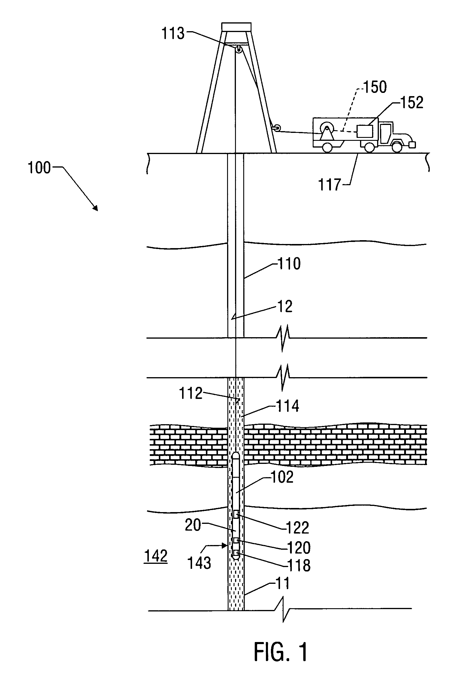
[0016]FIG. 1 illustrates a system 100 for detecting fluid flow into a wellbore. The system 100 shows a downhole tool 100 placed in a wellbore 110 utilizing a tool carrying member 112, which may be a wireline, tubing, slick line or any other suitable carrying member. The wellbore 110 may contain air or a liquid, such as a drilling fluid or production fluid, as a medium 118. The tool 102 is shown to include a lower acoustic sensor arrangement or set 120 and an upper acoustic sensor arrangement or set longitudinally spaced apart from the lower sensor set by a known distance. Each sensor arrangement may include multiple ultrasonic sensors, each such sensor further may be an ultrasonic sensor. The sensors in each sensor arrangement may be placed circumferentially around the tool 102 to provide a full coverage o...


PUM


Abstract

The method and apparatus of the present invention provides for detecting a flow of a formation fluid entering into a wellbore. An ultrasonic sensor is placed in a wellbore. The sensor has a resonant member that is exposed to a fluid in the wellbore. At a location in the wellbore, acoustic energy is measured wherein the acoustic energy is related to turbulence from formation fluid entering the wellbore. In another embodiment of the invention a tool is provided for detecting a flow of a formation fluid into a downhole location in a wellbore. The ultrasonic sensor has a resonant member that is adapted to be in contact with a fluid in the wellbore. The sensor generates electrical signals when exposed to ultrasonic turbulences caused by a formation fluid entering into the wellbore. A processor processes the electrical signals to detect the flow of the formation fluid entering into the wellbore.

Description

FIELD OF THE INVENTION[0001]The invention relates generally to the field of the evaluation for hydrocarbons in a wellbore, and more specifically to a method and apparatus for detecting flow of formation fluids into wellbores.BACKGROUND OF THE INVENTION[0002]Downhole tools, such as wireline tools, bottom hole assemblies attached to a drill string, each having a variety of sensors are commonly utilized to determine a variety of parameters of interest relating the subsurface formations, including detection of formation fluids flowing into the wellbores. It is useful to detect the presence, extent, and location (depth) of the wellbore fluids entering a wellbore. Such information may be utilized for completing the wells, performing remedial work and / or to determine one or more characteristics of the reservoir or the formation.[0003]An increase in the demand of natural gas has led to the need to complete low volume gas wells. This demand has caused the oil and gas exploration industry to ...

Claims


Application Information

Patent Timeline
Patent Type & Authority Patents(United States)
IPC IPC(8): E21B47/08
CPCE21B47/101G01N29/036G01N29/222G01V1/44G01N2291/014G01N2291/02881E21B47/107
Inventor STEINSIEK, ROGER
Owner BAKER HUGHES HLDG LLC
Why Eureka
Try Eureka