Printing machines having at least one machine element that can be adjusted by a setting element

a technology of setting elements and printing machines, applied in the field of printing machines, can solve the problems of complex levels, insufficiently addressing what actually happens in practice, and forming a complex level, and achieve the effects of stable operating state, good quality, and rapid effective control

Inactive Publication Date: 2008-12-16
KOENIG & BAUER AG
View PDF55 Cites 21 Cited by
  • Summary
  • Abstract
  • Description
  • Claims
  • Application Information

AI Technical Summary

Benefits of technology

[0019]The object of the present invention is to create printing machines having at least one machine element that can be adjusted with a setting element, wherein a quality of the printing can be adjusted and will be stable at the adjusted level in the print run. The object is attained according to the invention though provision of printing machines wherein an optical detection device having a sensor that is directed toward a surface of a printing substrate printed in the printing machine detects the quality of the printing on the printing substrate transported through the printing machine. A control device receives data from the optical detection device and uses the setting element (to adjust the at least one machine element based upon a difference between a quality of the printing that is preset as the target value and the quality of the printing that is detected by the optical detection device as the actual value, in a manner that serves to minimize the difference between the target value and the actual value.
[0022]The benefits that can be achieved with the invention consist especially in that a quality of the printing can be adjusted and can be maintained at the adjusted level in the print run. An interfering factor that negatively influences the quality of the printing is effectively counteracted in a synchronized manner, viewed with other interfering factors, as soon as the detection device detects the negative effect of the interfering factor on the quality of the printing. This is possible because the detection device is capable of detecting all interfering factors that affect the quality of the printing. A simultaneous detection of all interfering factors, both in real time and near the location at which the quality of the printing is produced, enables a rapidly effective control from an evaluation of the output signal from only one detection device, so that with respect to the printing, a stable operating state producing good quality can be achieved after only a very short time. The detection of the quality of the printing in its entirety, combined with an evaluation of the data that correlate with it with respect to multiple, preferably all, interfering factors that adversely affect the quality of the printing, means a substantial reduction of work for an operator operating the printing machine, as he / she is not required to monitor and / or operate a multitude of different control and / or regulating devices.

Problems solved by technology

This does not adequately address what actually occurs in practice.
Clients ordering printed products are placing ever increasing demands on the quality of printed products created using printing machines, wherein the concept of the quality of a printing, through properties shown in samples of the printing, forms a complex level.
In the print run even high-precision machine elements of the printing machine are subject, for example, to changes caused by wear and tear, and even high-quality materials processed in the print run are subject, for example, to thermal changes.
Thus, the structural dimensions of printing machines for the most part cannot alone guarantee a reproducibility of the copies that make up the printing.
This approach results in a complex control system for the printing machine, in which the quality of the printing is viewed as a controlled process that inhibits interfering factors and must be regulated.

Method used


Image

  • Printing machines having at least one machine element that can be adjusted by a setting element
  • Printing machines having at least one machine element that can be adjusted by a setting element
  • Printing machines having at least one machine element that can be adjusted by a setting element

Examples


Embodiment Construction

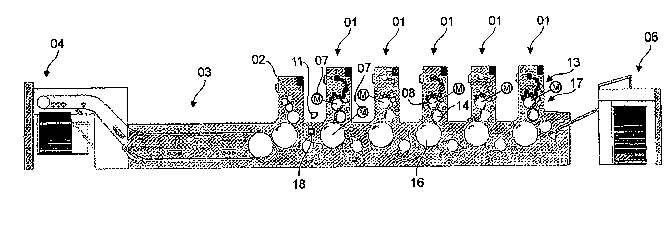
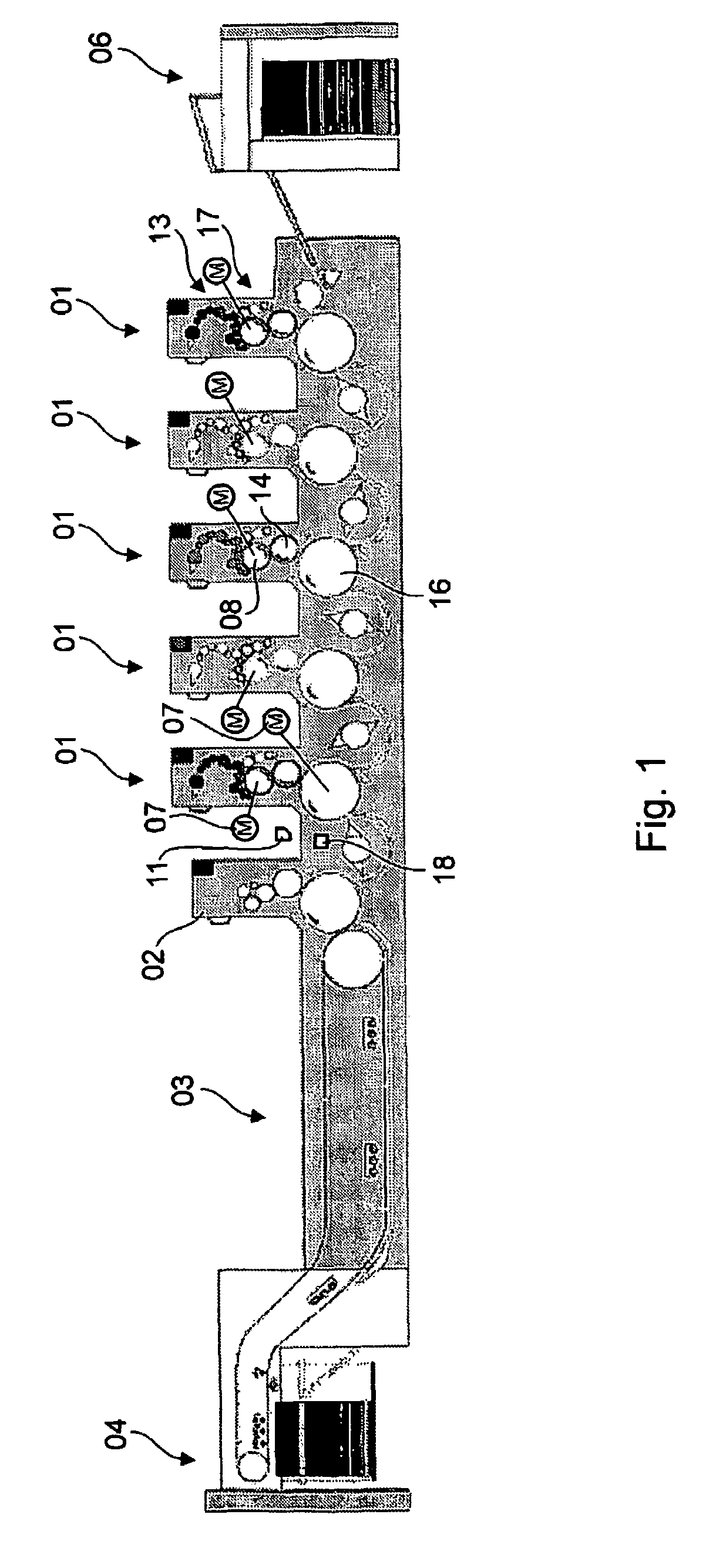
[0027]FIG. 1 shows a printing machine, which is designed by way of example as a sheet-fed printing machine. Alternatively, however, the printing machine may also be designed as a web-fed printing machine. The printing machine is designed especially as an offset printing machine. However, it may also be provided that the printing machine prints using a waterless offset printing process. The printing machine illustrated by way of example in FIG. 2 is a waterless printing machine, i.e. one that prints without the addition of a dampening agent.

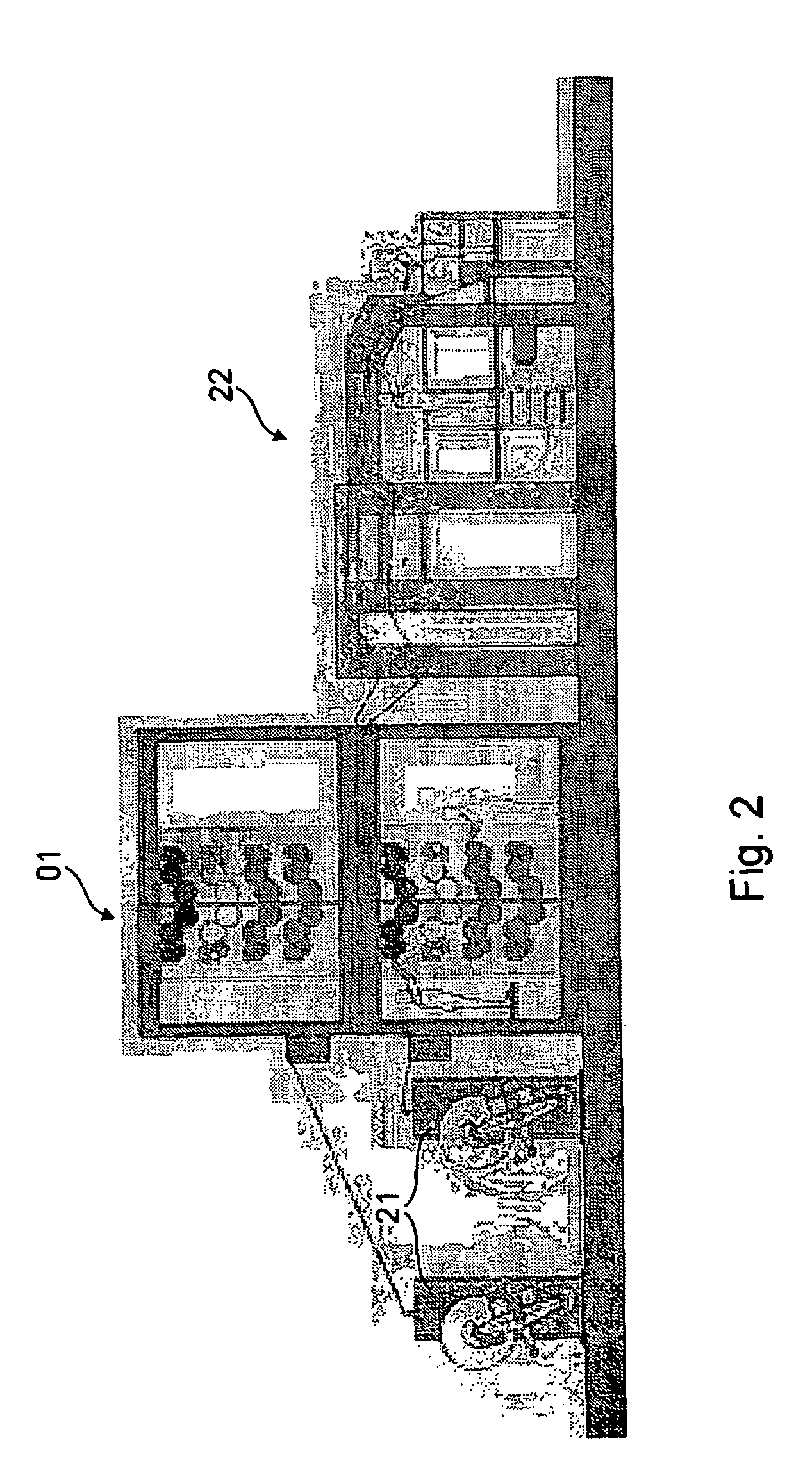
[0028]The printing machine is preferably equipped with multiple printing couples 01, each of which prints on the same printing substrate with one printing ink. In the example in FIG. 1 five printing couples 01 are provided in the direction of transport of the printing substrate, arranged sequentially according to the unit construction principle. These are followed by a coating unit in the form of a tower coater 02, along with a delivery extension ...


PUM


Abstract

A printing machine has at least one machine element which can be adjusted by the use of a setting element. An adjustment of the one machine element has an effect on the quality of the printing performed by the printing machine. An optical detection device, which includes a sensor that is oriented toward the surface of a material which is being printed, detects the quality of the printing. A controlling device receives data from the optical sensor and adjusts, together with the setting element, the at least one machine element based on a difference between a quality of the printing which has been specified as a set value and the quality of the printing detected as an actual value by the optical detection device. This adjustment is done to manage the differences between the set value and the actual value. The control is based on the fact that the quality of the printing is detected in its entirety by the optical detection device and the data is evaluated with regard to disturbing influences acting upon the quality of the printing.

Description

CROSS REFERENCE TO RELATED APPLICATIONS[0001]This application is a US National Phase filing under 35 U.S.C. 371 of International Application No. PCT / EP2005 / 051234, which was filed on Mar. 17, 2005 and claims priority on DE 10 2004 014 533.4, filed Mar. 23, 2004, DE 10 2004 035 787.0, filed Jul. 23, 2004 and DE 10 2004 049 079.1, filed Oct. 8, 2004, all of which are incorporated by reference in their entirety.BACKGROUND OF THE INVENTION[0002]1. Field of the Invention[0003]The present invention relates to printing machines having at least one machine element that can be adjusted using a setting element, to affect a quality of a printing performed by the printing machine, wherein an optical detection device having a sensor that is directed toward a surface of a printing substrate printed in the printing machine detects the quality of the printing during the transport of the printing substrate through the printing machine, and wherein a control device that receives data from the optical...

Claims


Application Information

Patent Timeline
Patent Type & Authority Patents(United States)
IPC IPC(8): B41F31/00B41F13/14B41F31/04B41F33/00
CPCB41F31/045B41F33/0045B65H2557/2644
Inventor JESCHONNECK, HARALD HEINZ PETERBUDACH, STEFAN ARTHURTURKE, THOMASWILLEKE, HARALD HEINRICHBERNARD, ANDREAS EWALD HEINRICH
Owner KOENIG & BAUER AG
Why Eureka
Try Eureka