Fold-down wall-table knee-brace

a knee-brace and wall-table technology, applied in the field of collapsible table construction, can solve the problems of limited weight-bearing capacity of hinges, obstructing foot space below the open table, and inability to support a heavy load in the hinge configuration

Inactive Publication Date: 2008-12-16
HAUCK ROBERT F
View PDF20 Cites 10 Cited by
  • Summary
  • Abstract
  • Description
  • Claims
  • Application Information

AI Technical Summary

Benefits of technology

[0020]Yet another object of the present disclosure is to provide a simple knee-brace for a collapsible table.
[0021]Yet another object of the present disclosure is to provide a durable knee-brace for a collapsible table.
[0023]Yet another object of the present disclosure is to provide a knee-brace for a collapsible table which is easily maintained.
[0024]Yet another object of the present disclosure is to provide a knee-brace for a collapsible table which is economical to manufacture.
[0029]An advantage of the present disclosure is a knee-brace configuration that can easily support a 200 lb load on the outer edge of a 32-inch wide hinged shelf or collapsible table.
[0030]Another advantage of the disclosed knee-brace is that it is readily fabricated, preferably, from high-density solid plastic and hidden stainless-steel pins and hinge-brackets both for strength and for durability in outdoor applications.

Problems solved by technology

Configured in this way, such table legs obstruct foot space below the opened table.
Furthermore, while there exist commercially available hinges for supporting a collapsible shelf from a wall, such hinges possess limited weight-bearing capacity.
This hinge configuration cannot support a heavy load because torque induced at the hinge-pin by a loaded shelf can easily exceed the bending threshold of a metal stop which supports the shelf in the locked configuration.
However, because in many instances mechanical requirements of structures are moderate or may be accommodated by an appropriate design or hidden structural supports, the solid plastic, wood-alternative material's lesser mechanical rigidity does not prevent its use in such structures.

Method used


Image

  • Fold-down wall-table knee-brace
  • Fold-down wall-table knee-brace
  • Fold-down wall-table knee-brace

Examples


Embodiment Construction

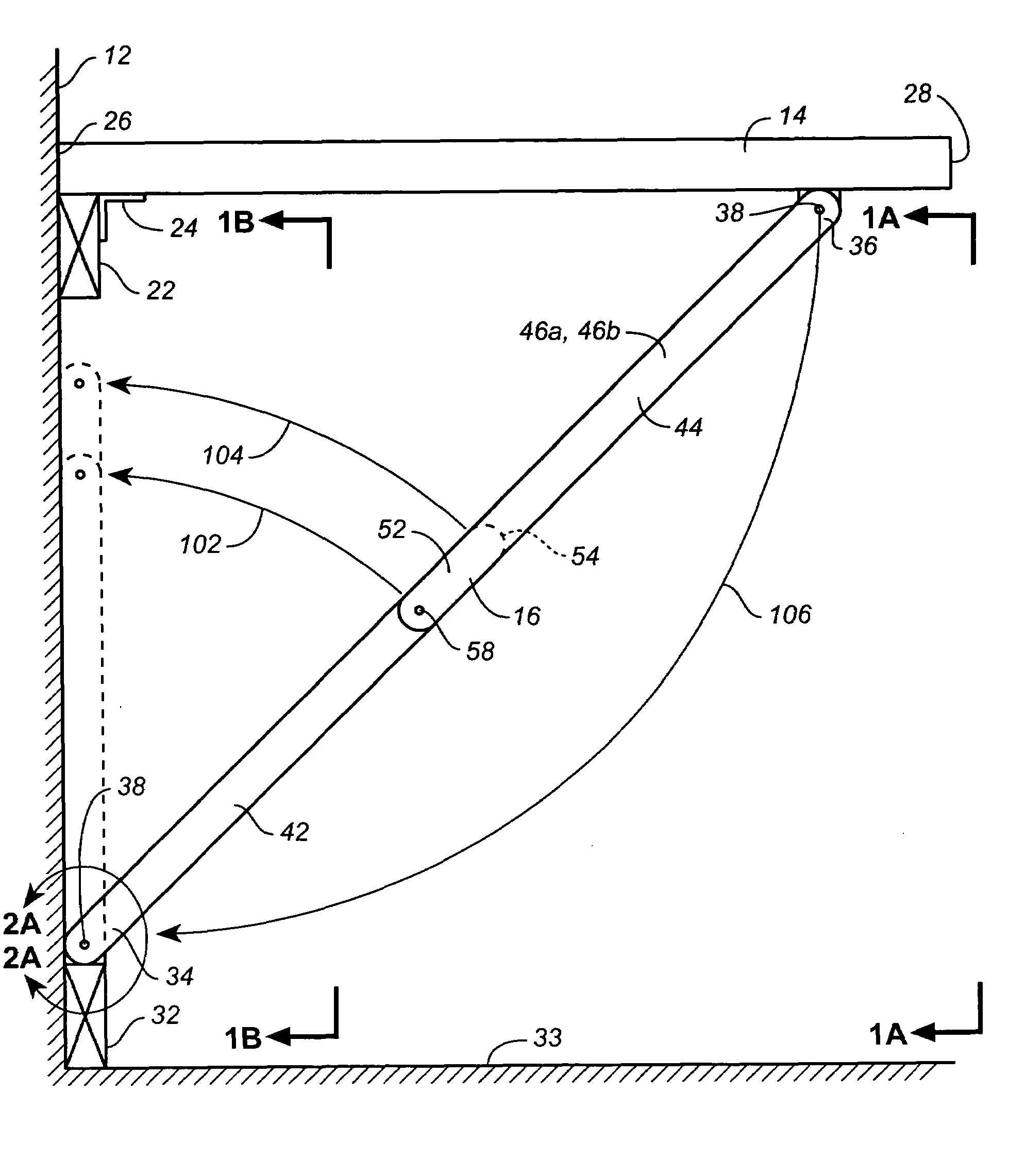
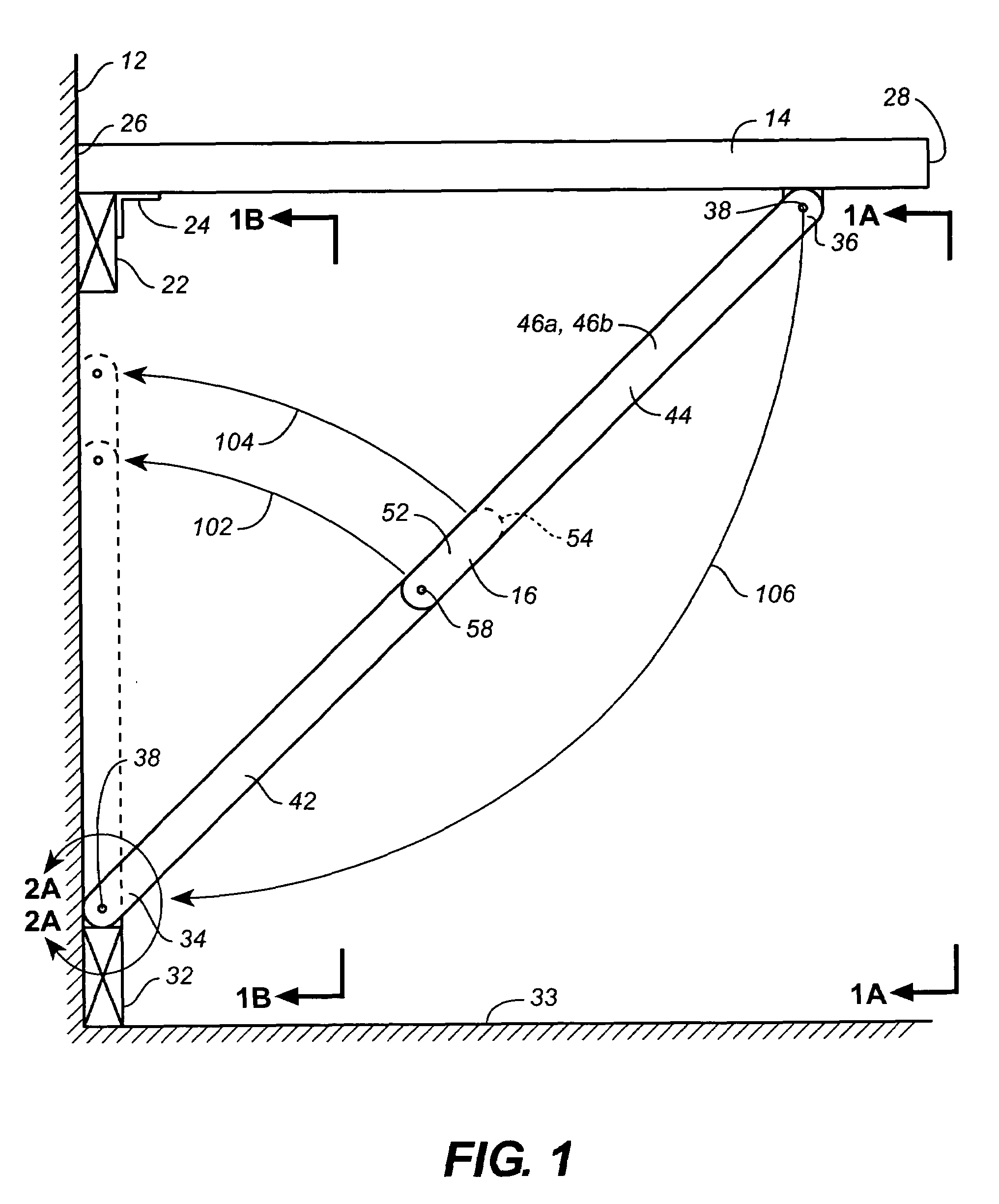
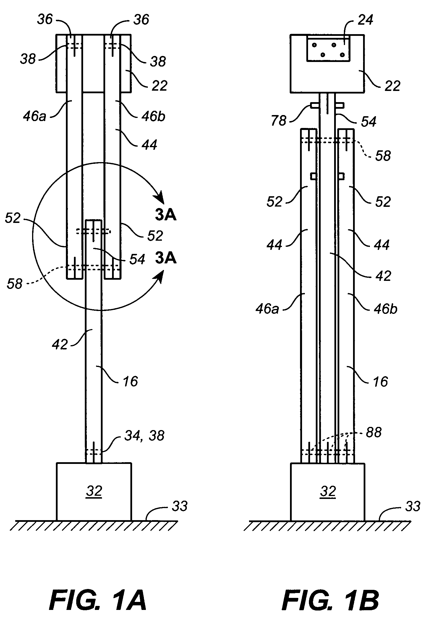
[0040]FIG. 1 illustrates a side view of a wall 12, a table 14, and a knee-brace 16 of the present disclosure. In FIG. 1, the knee-brace 16 supports the table 14 in a horizontal orientation in which the table 14 projects outward from the wall 12 or other support. FIG. 1A is a front view depicting the knee-brace 16 supporting the table 14 when raised to a horizontal orientation projecting outward from the wall 12 or other support. FIG. 1B is also a front view that, however, depicts the knee-brace 16 when the table 14 has been lowered to an orientation in which the table 14 is collapsed against the wall 12.

[0041]Immediately beneath the table 14 where it abuts the wall 12, a top-block 22 is fastened to the wall 12, with a conventional butterfly-hinge 24 being fastened both to the table 14 and to the top-block 22. The table 14 is preferably hinged to the top-block 22 so a back-edge 26 of the table 14 aligns flush with the wall 12 when the table 14 is raised to a horizontal orientation. C...


PUM


Abstract

A foldable knee-brace for support a table having an edge secured to a wall. The knee-brace includes first and second struts. The second strut includes a pair of parallel bars. Ends of the bars are disposed on opposite sides of an end of the first strut, and hinged thereto. Pockets formed into each bar's side surface are positionable adjacent to the first strut's end for receiving an end of a locking-pin carried at and projecting outward from the first strut's end. Ends of the first strut and second strut's bars furthest from the hinge are equipped for hinged fastening respectively to:a. the table near a second edge thereof furthest from the wall; andb. to the wall below the table's first edge.Configured in this way, the knee-brace folds between the table and the wall when the table is collapsed adjacent to the wall.

Description

CLAIM OF PROVISIONAL APPLICATION RIGHTS[0001]This application claims the benefit of U.S. Provisional Patent Application No. 60 / 588,215 filed on Jul. 15, 2004.BACKGROUND[0002]1. Technical Field[0003]The present improvement relates to collapsible table constructions, and more specifically to such tables which are secured along one edge to a wall or other support to project outward therefrom and are adapted to be placed into a collapsed orientation against the wall.[0004]2. Description of Background Art[0005]A need exists for supporting a loaded 32-inch wide wall-mounted fold-down table which minimizes interference with access to the erected table. There exist support hinges for legs of free-standing tables, but those legs, which are attached to the table with such hinges, stand vertically when the legs are in the opened position supporting the table. Configured in this way, such table legs obstruct foot space below the opened table. Furthermore, while there exist commercially availabl...

Claims


Application Information

Patent Timeline
Patent Type & Authority Patents(United States)
IPC IPC(8): A47B23/00
CPCA47B5/04
Inventor HAUCK, ROBERT F.
Owner HAUCK ROBERT F
Why Eureka
Try Eureka