Two handed power driven flossing apparatus with removable head for attachment to power driven toothbrush

a technology of power-driven flossing and a removable head, which is applied in the field of electric tooth flossing devices, can solve the problems of reducing the use of flossing operation, so as to achieve convenient use and safe

Inactive Publication Date: 2008-12-16
NYGREN JR WILLIAM D
View PDF24 Cites 25 Cited by
  • Summary
  • Abstract
  • Description
  • Claims
  • Application Information

AI Technical Summary

Benefits of technology

[0012]A general object of the present invention is to provide an electric dental flosser

Problems solved by technology

This flossing operation, while necessary for dental health, is often neglected in practice because of the difficulty of holding onto the wet saliva-coated floss, the difficulty and clumsiness of inserting a major portion of both hands into the back of the mouth and finally, the difficulty of pulling the floss between tightly spaced teeth.
Although these one-handed devices appear to be a simple solution, they, in fact, greatly restrict the ability to wrap the floss around and clean the sides of the teeth.
Many of these one-handed devices also incorporate rather complicated methods for attaching, replacing or advancing used floss across the “V” of the flossing device.
The difficulty with this motion is that if the floss is loose enough to wrap around the teeth for proper cleaning, then the vibratory motion of the yoke may not be oriented such that it is able to induce to desired reciprocating motion of the floss along its length.
The problem with flossers of th

Method used


Image

  • Two handed power driven flossing apparatus with removable head for attachment to power driven toothbrush
  • Two handed power driven flossing apparatus with removable head for attachment to power driven toothbrush
  • Two handed power driven flossing apparatus with removable head for attachment to power driven toothbrush

Examples


Embodiment Construction

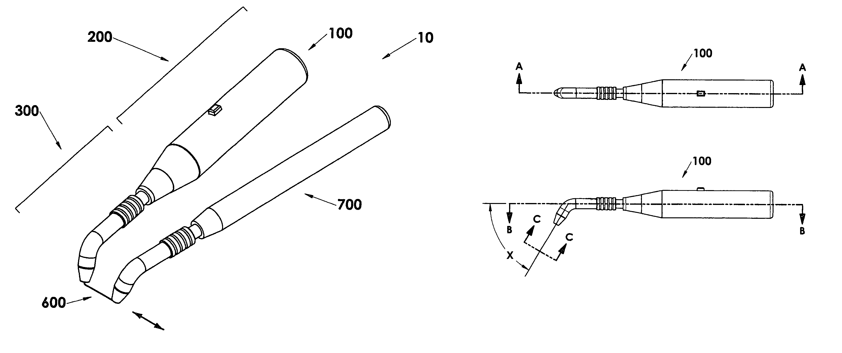
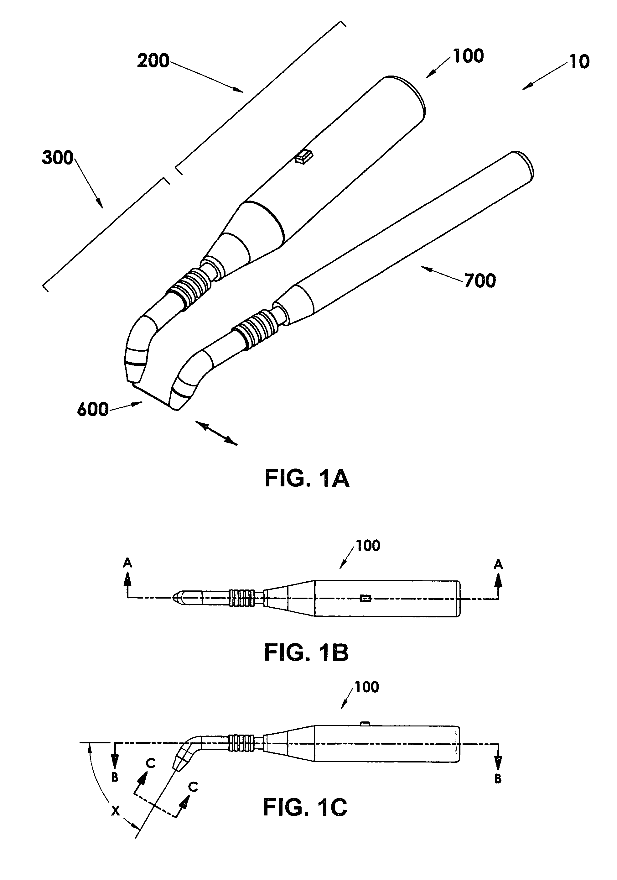
[0102]Reference will now be made to the drawings, wherein the drawings are for the purposes of illustrating various embodiments of the invention only and not for purposes of limiting the same.

[0103]A preferred embodiment of the electric dental flosser of the present invention is shown generally as 10 in FIG. 1A. The flosser 10 generally includes a powered unit 100 (e.g., a first handle), a non-powered unit 700 (e.g., a second handle), and a disposable floss assembly 600. Further, the powered unit 100 is comprised of a power or drive unit 200 and a flossing head 300.

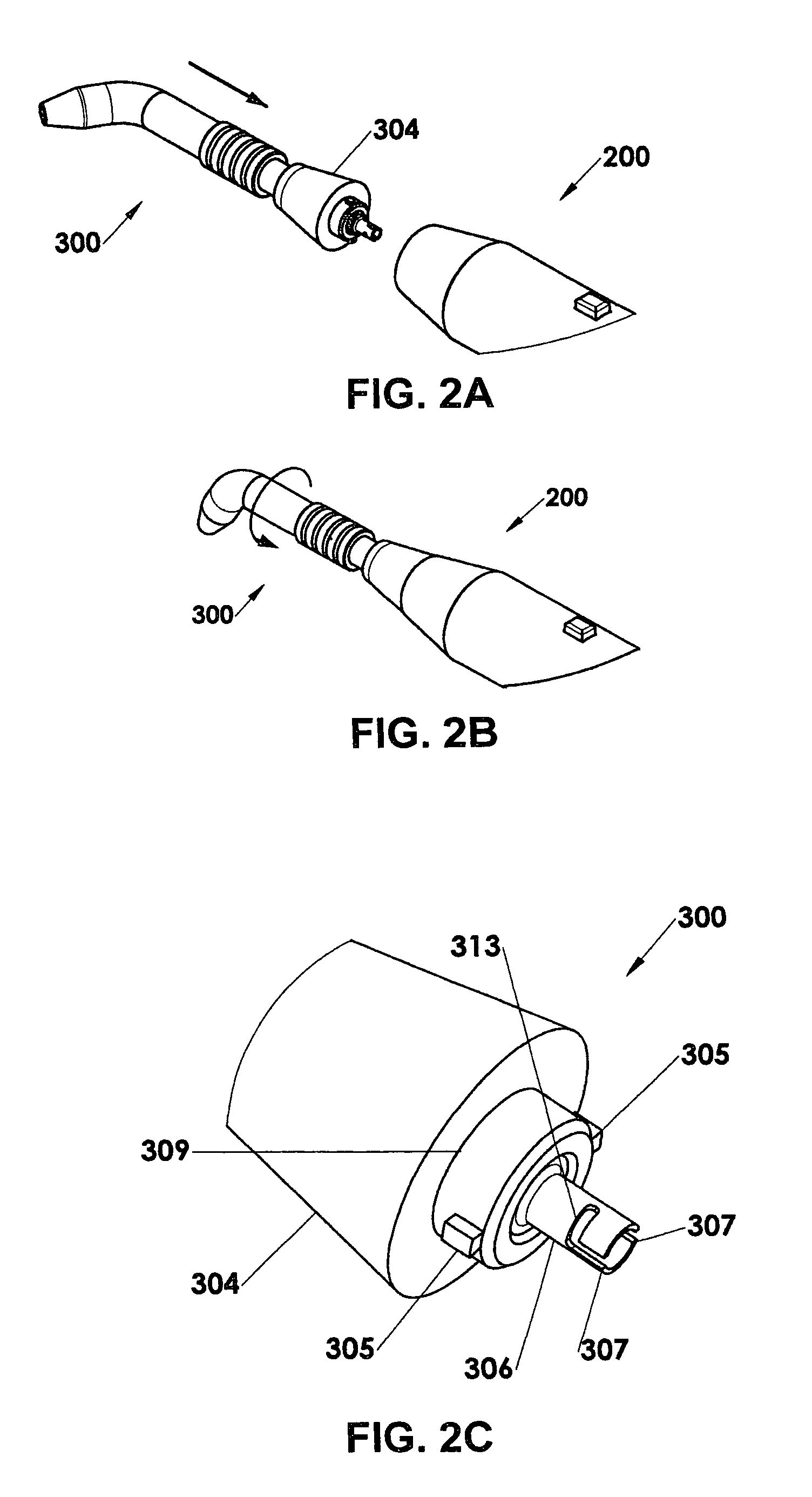
[0104]As shown in FIGS. 2A, 2B and 2C the electric flosser 10 includes a drive unit 200 which is detachably connected to the flossing head 300. The drive unit 200 may be in the form of that which is used with a commercially available powered toothbrush. The flossing head 300 would simply replace the toothbrush attachment in this case. In any case, to connect the flossing head 300 to the drive unit 200, the user aligns cyl...


PUM


Abstract

An electric flossing apparatus comprising a flossing head which is detachably connected to a handle containing a reciprocating drive unit, a non-powered second handle to allow for the increased controllability of two-handed powered flossing and a disposable floss assembly that can be easily be attached to or released from the flossing head and handle. The floss is releasably attached to the flossing head in a manner that allows reciprocating motion to be imparted along the length of the floss no matter which direction that the floss exits the end of the flossing head or the shape of the path it takes. By using both hands for flossing the floss may be pulled straight and tensioned to facilitate insertion between tightly spaced teeth and then wrapped around a tooth to facilitate cleaning of the front, sides, and back of each tooth above, near, or just below the gum line. The reciprocating motion is imparted to the floss whenever the floss is tensioned. The intensity of the motion is then controlled by the amount of tension and the “rigidity” of the users grip on the two handles. The drive unit handle assembly may be from an inexpensive commercially available electric toothbrush such as a Crest Spinbrush™.

Description

CROSS-REFERENCE TO RELATED APPLICATIONS[0001]This patent application claims priority under 35 U.S.C. §119 to U.S. Provisional Patent Application Ser. No. 60 / 582,773, that is entitled “FLOSSING APPARATUS”, that was filed on Jun. 25, 2004, and the entire disclosure of which is being incorporated by reference herein.FIELD OF THE INVENTION[0002]The present invention relates generally to electric tooth flossing devices. More particularly, it relates to an improved two-handed powered flossing device which detachably connects to a drive unit which can also be used to power an electric toothbrush.BACKGROUND OF THE INVENTION[0003]The dental profession has long recommended cleaning one's teeth with dental floss as a necessary part of daily dental hygiene. It is widely recognized that the proper use of dental floss is an effective means for preventing the buildup of plaque, gum disease and tooth decay.[0004]Dental hygienists typically recommend wrapping a short length dental floss around the f...

Claims


Application Information

Patent Timeline
IPC IPC(8): A61C15/00
CPCA61C15/047
Inventor NYGREN, JR., WILLIAM D.
Owner NYGREN JR WILLIAM D
Why Eureka
Try Eureka