Three-wheeled vehicle having a split radiator and an interior storage compartment

a three-wheeled vehicle and radiator technology, applied in vehicles, propulsion cooling, propulsion parts, etc., can solve problems such as limping home functions, and achieve the effect of reducing the amount of hoses and other connections, and increasing the storage area

Inactive Publication Date: 2008-12-16
BOMBARDIER RECREATIONAL PROD INC
View PDF16 Cites 52 Cited by
  • Summary
  • Abstract
  • Description
  • Claims
  • Application Information

AI Technical Summary

Benefits of technology

[0015]It is another object of the present invention to provide a three-wheeled straddle type vehicle having improved maneuverability and control by comparison with conventional three wheeled vehicles.
[0024]In response to the foregoing challenges, applicants have developed a novel three-wheeled vehicle that offers enhanced cooling while offering improved maneuverability and control with a low center of gravity. In particular, the present invention relates to a three-wheeled straddle-type vehicle having two wheels in the front of the vehicle and one wheel in the rear of the vehicle. The cooling system includes a split radiator arrangement whereby the cooling system can be located lower to the ground to improve the vehicle's center of gravity. Furthermore, the relocation of the cooling system from the front to the sides of the vehicle opens up the front portion of the vehicle for storage, which is lacking in the prior art vehicles.
[0025]A notable aspect of the three-wheeled vehicle of the present invention is that it is designed to operate with an engine capable of generating 80-135 horsepower or even greater and that it is intended for road use. Many of the three-wheeled vehicles heretofore available have been mostly capable of 30 horsepower (hp), and especially less than 100 hp, due to limitations in the structural strength of the frame and the maneuverability and stability of the vehicle. The novel head pipeless frame assembly of the three-wheeled vehicle of the present invention provides sufficient structural rigidity to withstand the forces experienced during high performance operation of the vehicle. Further, with the improved positioning of the center of gravity of the rider vis-á-vis the center of vehicle, the present invention alleviates the problems of instability and lack of control in sharp turns or during abrupt directional changes.
[0029]Each radiator may include a cooling fan located on the rear surface of the radiator. The cooling fans are provided to direct air from the radiators away from the riders. The fans preferably direct the air rearwardly under the vehicle to reduce drag. This arrangement also serves to flush hot air from beneath the vehicle, which may assist in engine cooling.
[0032]The vehicle further includes a fairing assembly enclosing at least the front portion of the frame. The fairing assembly includes a first radiator enclosure for enclosing at least a portion of the first radiator and a second radiator enclosure for enclosing at least a portion of the second radiator. As discussed above, the radiator enclosures may be provided with selectively operable units to direct warm air from the radiators onto the driver during cooler operating conditions. Since the vehicle is intended for road use, it is desirable to provide a storage compartment for the rider to store objects during use (e.g., a briefcase, backpack, etc.) and while not in use (e.g., a helmet). The front portion of the frame includes a cavity, which forms a storage compartment. The fairing assembly includes a removable cover to provide access to the cavity. The cavity may provide access to at least a portion of the internal combustion engine and an engine service center. The location of the radiators on the side of the vehicle increases the size of the storage area.
[0033]The vehicle further includes an air inlet passageway formed in the front portion of the frame. An oil cooler assembly is connected to the internal combustion engine for cooling engine oil circulating through the internal combustion engine. A flow of air is directed through the air inlet passageway over the oil cooler assembly to cool the oil in the oil cooler assembly. The oil cooler assembly is located between the first radiator and the second radiator. The provision of the cooling passageway permits the oil cooler to be located closer to the engine, which reduces the amount of hoses and other connections necessary to link the oil cooler to the engine. The air inlet passageway may also be used to direct a flow of air onto the radiators. In this variation, the radiators are still located on opposite sides of the vehicle, but are substantially parallel to the longitudinal axis of the vehicle. A flow director directs the flow of air from the inlet towards the radiators.

Problems solved by technology

Furthermore, the relocation of the cooling system from the front to the sides of the vehicle opens up the front portion of the vehicle for storage, which is lacking in the prior art vehicles.
Many of the three-wheeled vehicles heretofore available have been mostly capable of 30 horsepower (hp), and especially less than 100 hp, due to limitations in the structural strength of the frame and the maneuverability and stability of the vehicle.
Such a parallel arrangement, however, provides a limp home function in the event of a failure of one of the radiators.

Method used


Image

  • Three-wheeled vehicle having a split radiator and an interior storage compartment
  • Three-wheeled vehicle having a split radiator and an interior storage compartment
  • Three-wheeled vehicle having a split radiator and an interior storage compartment

Examples


Embodiment Construction

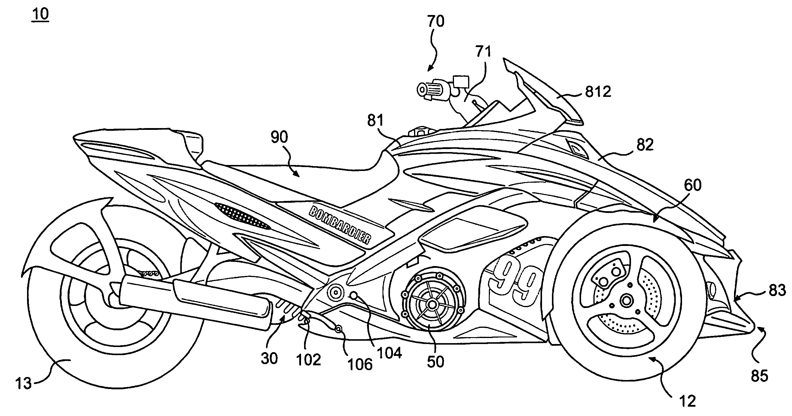
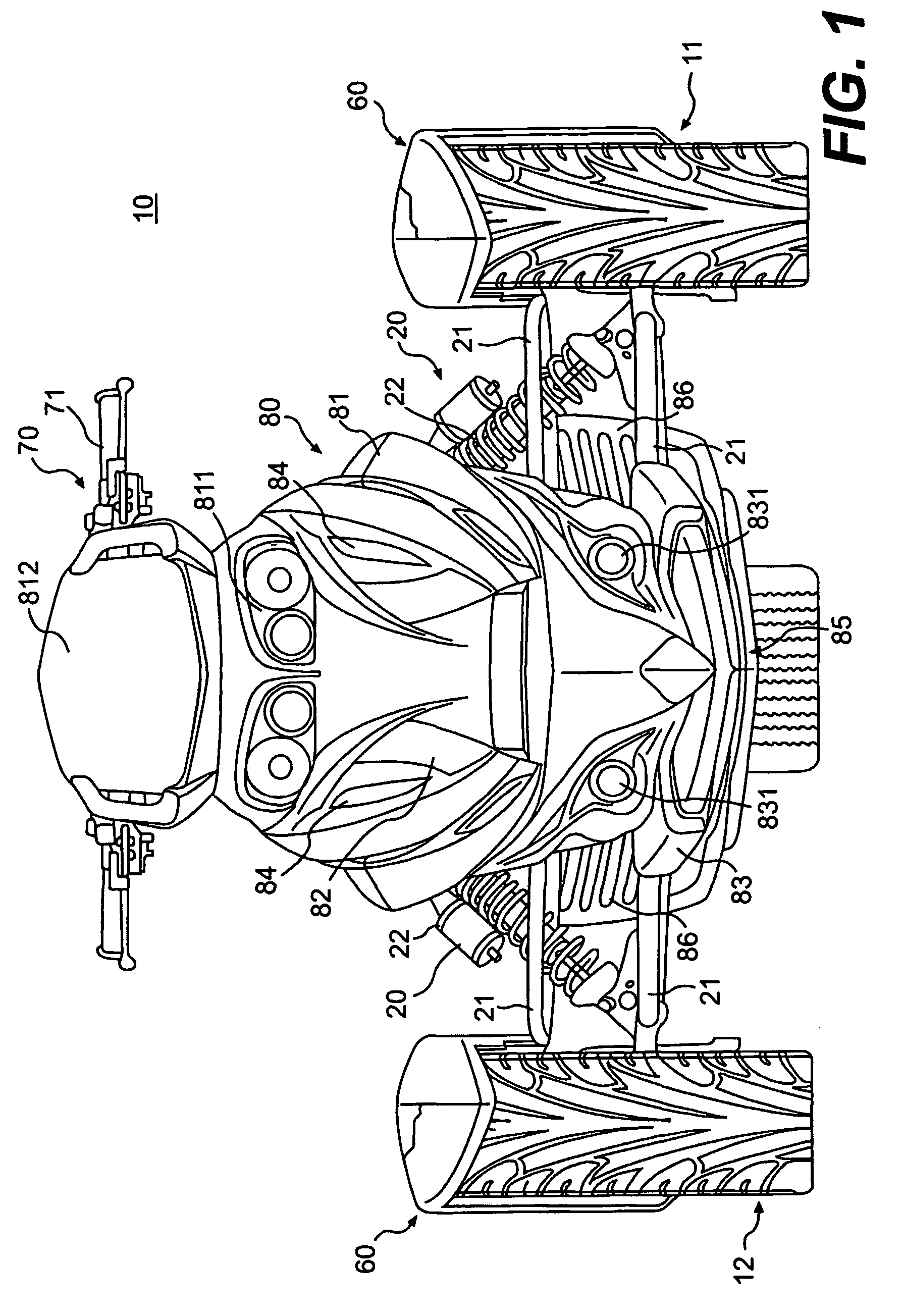
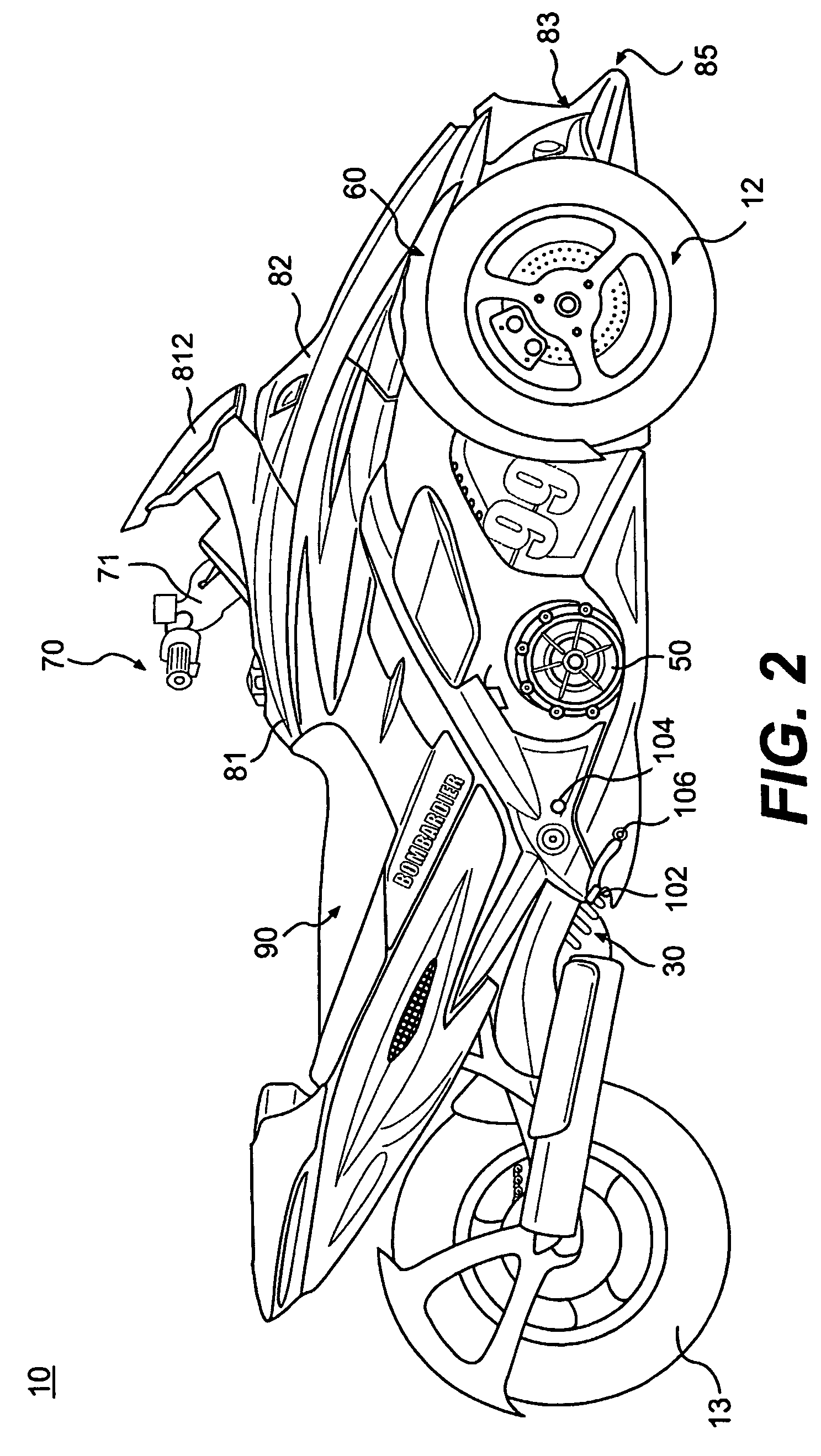
[0054]A three-wheeled straddle type vehicle 10 in accordance with the present invention is generally illustrated in FIGS. 1-3. The vehicle 10 is designed with a straddle-type seat assembly 90 that preferably accommodates two adult-sized riders, a driver and a passenger. While the vehicle 10 is not designed to accommodate more than two adult-sized riders, the present invention contemplates that the design of vehicle 10 may be changed easily to accommodate more than two adult-sized riders.

[0055]It should be noted that the conventions “left,”“right,”“front,”“rear,”“up,” and “down” are defined according to the normal, forward travel direction of the vehicle being discussed. As a result, the “left” side of a vehicle corresponds to the left side of a rider seated in a forward-facing position on the vehicle.

[0056]The vehicle 10 is designed along a longitudinal axis and includes a left front wheel 11, a right front wheel 12 and a rear wheel 13. The front wheels 11 and 12 are equally offset ...


PUM


Abstract

A novel three-wheeled straddle type vehicle for operation by at least one rider is disclosed having a split radiator (52, 53) located on opposite sides of the vehicle frame. The location of the split radiator (52, 53) on the sides of the frame create a storage compartment in the front portion of the vehicle frame.

Description

CROSS REFERENCE TO RELATED APPLICATIONS[0001]This application is a national phase entry of International Application Number PCT / CA02 / 01565, filed Oct. 18, 2002, designating the United States of America. This application is also related to and claims priority to U.S. Provisional Patent Application Ser. No. 60 / 358,364, which was filed on Feb. 22, 2002.[0002]This application is also related to, but does NOT claim priority to, the following U.S. provisional applications that were filed on Feb. 22, 2002: No. 60 / 358,400; No. 60 / 358,394; No. 60 / 358,390; No. 60 / 358,395; No. 60 / 358,399; No. 60 / 358,436; No. 60 / 358,397; No. 60 / 358,439; No. 60 / 358,362; and No. 60 / 358,398. This application is also related to U.S. provisional application No. 60 / 358,737 filed on Feb. 25, 2002, U.S. Design Application 29 / 155,964 filed on Feb. 22, 2002, and U.S. Design Application 29 / 156,028 filed on Feb. 23, 2002. The entirety of the subject matter of these applications is incorporated by reference herein.BACKGROUN...

Claims


Application Information

Patent Timeline
Patent Type & Authority Patents(United States)
IPC IPC(8): B62K5/04B60K11/04
CPCB60K11/04B62K5/027B62K5/05B60Y2200/12B60Y2200/124
Inventor GUAY, ETIENNEFECTEAU, BERTHOLDAUBE, MARTINGIROUARD, BRUNO
Owner BOMBARDIER RECREATIONAL PROD INC
Why Eureka
Try Eureka