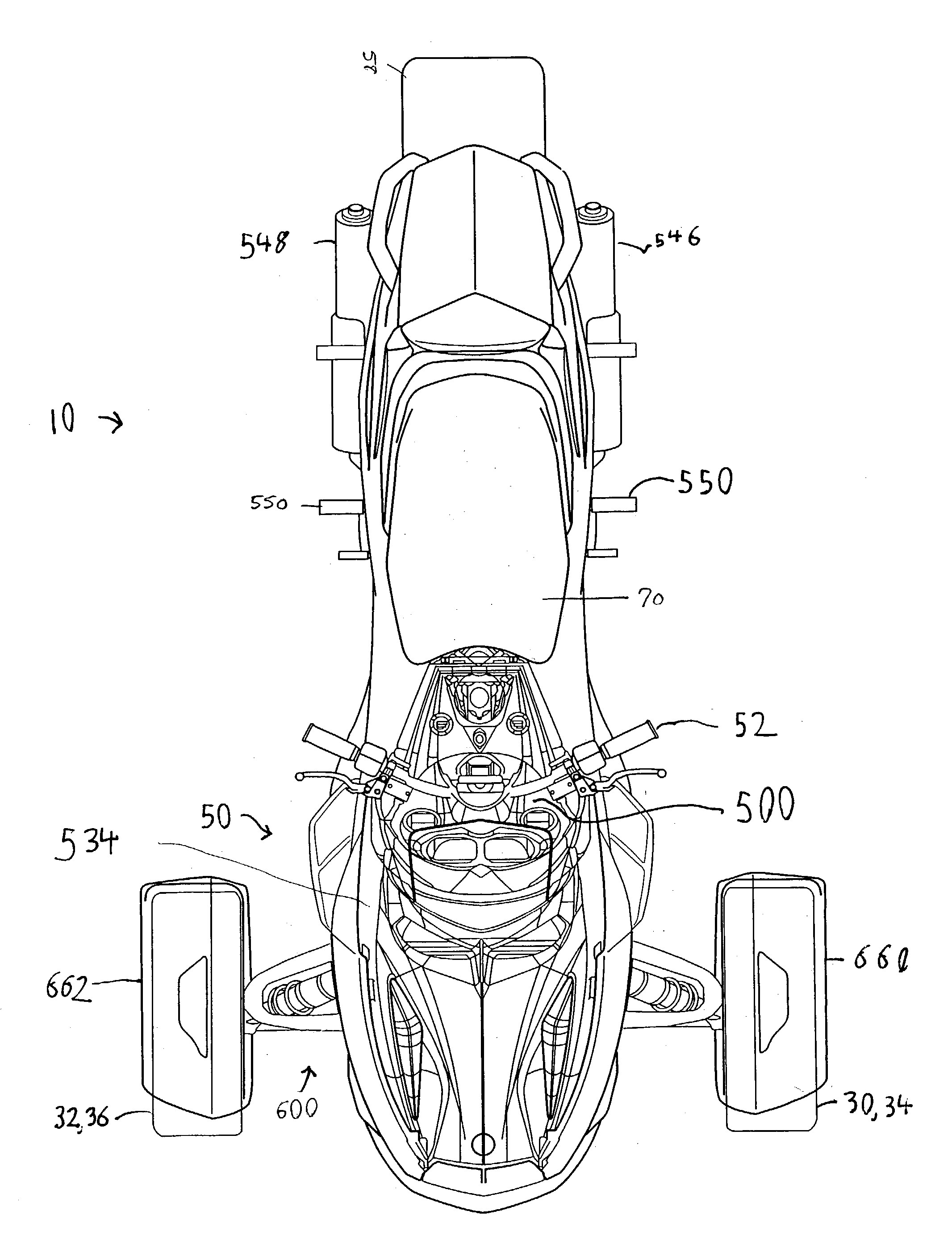
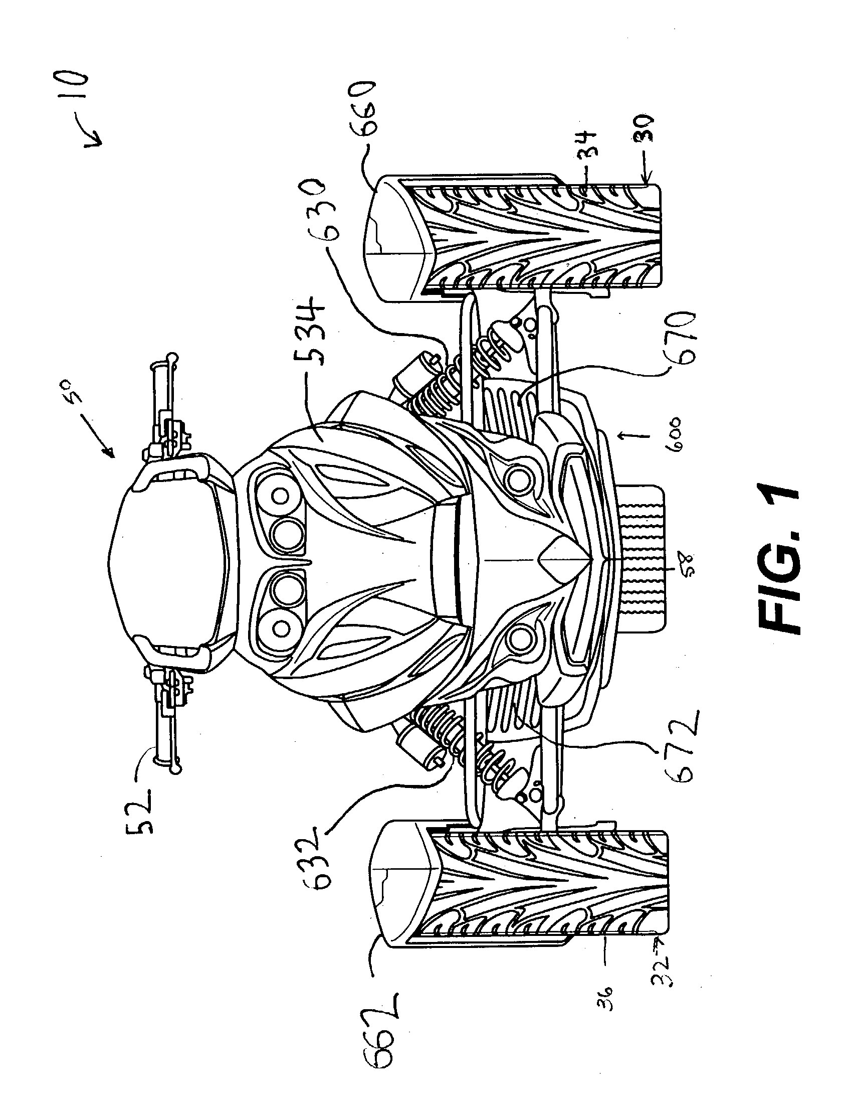
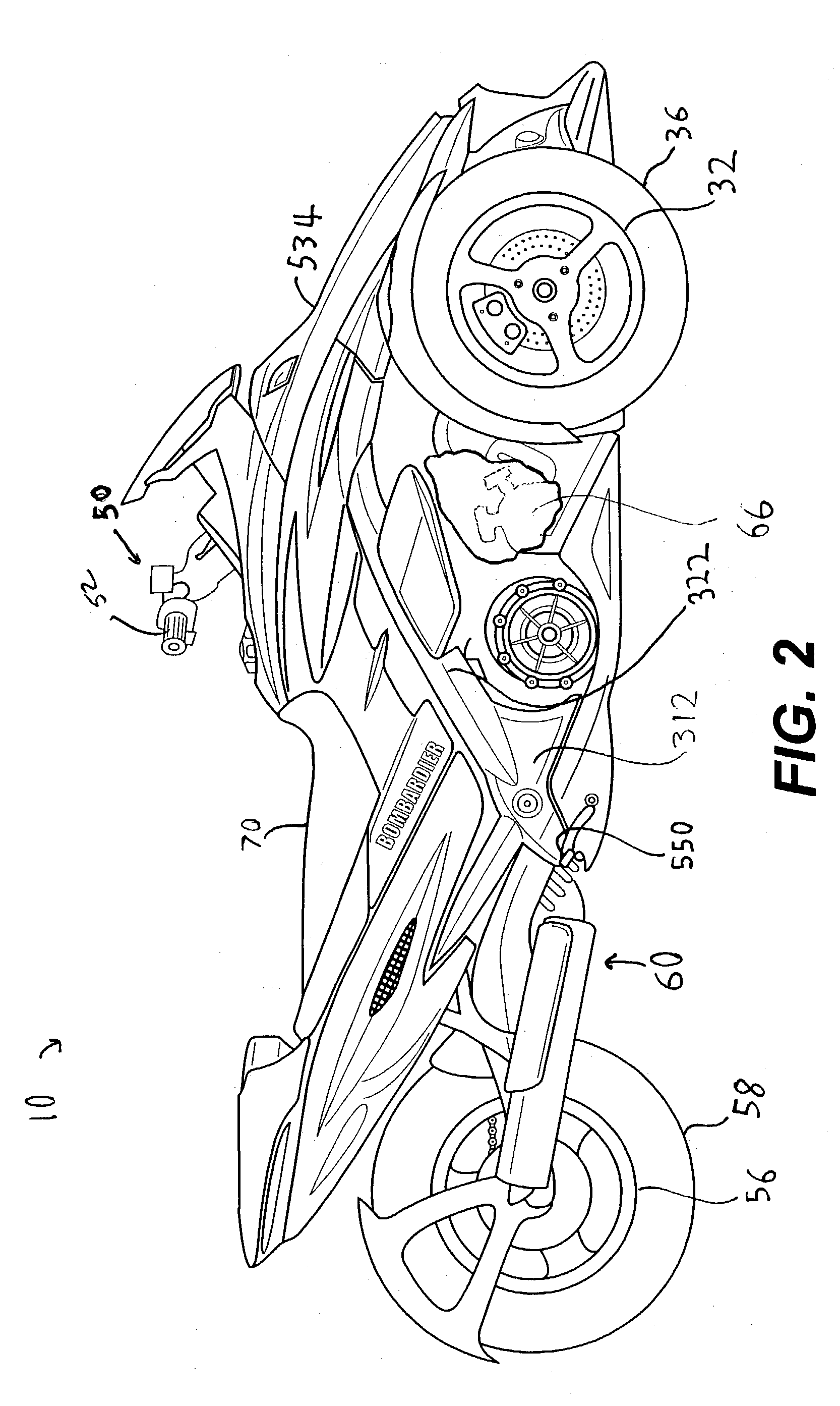
Frame configuration for a three-wheel vehicle

a three-wheel vehicle and frame technology, applied in the direction of belts/chains/gearrings, mechanical devices, belts/chains/gearrings, etc., can solve the problems of unrecognized vehicle frame, vehicle body is not expected to exhibit stability and maneuverability characteristics, and prior art is devoid of disclosur

Inactive Publication Date: 2004-02-26
BOMBARDIER RECREATIONAL PROD INC
View PDF67 Cites 76 Cited by
  • Summary
  • Abstract
  • Description
  • Claims
  • Application Information

AI Technical Summary

Problems solved by technology

Further, because the vehicle described in the '470 patent is based on a two-wheel motorcycle, its frame is not designed to accommodate the torsional stresses that result from the addition of a third wheel (second front wheel).
Consequently, the vehicle body is not expected to exhibit characteristics of stability and maneuverability when subjected to the types of high loads, bending moments, and stresses that would be exerted on the vehicle during operation.
The prior art is devoid of any disclosure for a frame of a three-wheeled vehicle specifically designed as a three-wheeled vehicle for road use.
The adapted motorcycle and snowmobile frames, while they are believed to be usable for a three-wheeled vehicle, are not designed specifically to react to the types of torsional and binding stresses that are expected to be encountered by a three-wheeled vehicle during use.
While the frame for that ATV was specifically designed for a three-wheeled vehicle, the frame

Method used


Image

  • Frame configuration for a three-wheel vehicle
  • Frame configuration for a three-wheel vehicle
  • Frame configuration for a three-wheel vehicle

Examples


first embodiment

[0103] FIG. 19 illustrates the upper spars 320, 322 contemplated to fall within the scope of the present invention. In this embodiment, the tubular member 800 comprises a concave portion 802 and a flat portion 804. Preferably, both the concave portion 802 and the flat portion 804 are made from aluminum or a metal where aluminum is at least a component (e.g., a composite material). Of course, as would be appreciated by those skilled in the art, any other suitable material may be substituted therefor, such as steel, magnesium or an alloy containing magnesium, titanium or an alloy containing titanium, a composite material, a ceramic, or a composite including carbon fibers. This list of materials is not meant to be exhaustive. To the contrary, the scope of the present invention is intended to encompass a wide variety of materials that may be used to manufacture the upper spars 320, 322 or any other portion of the frame assembly 300. Moreover, it is contemplated that the individual compo...

third embodiment

[0108] FIG. 21 illustrates a cross-section of a tubular member 818. Here, the tubular member defines a cavity 820 that is not bounded on all sides, as in the previous two embodiments. It is believed that the tubular member 818 will provide sufficient structural strength and rigidity as the previous example. However, this particular embodiment offers the advantage of decreased weight as compared to the previous examples.

fourth embodiment

[0109] FIG. 22 illustrates a tubular member 822 constructed in accordance with the teachings of the present invention. In this embodiment, the tubular member 822 forms a cavity 824 that is not bounded. This embodiment, therefore, is similar to the embodiment illustrated in FIG. 21. This embodiment differs from that embodiment in that it presents a curved cross-section, rather than an angular one, as in the embodiment illustrated in FIG. 21. While a generally semi-circular cross-section is illustrated for this embodiment, it is contemplated that the tubular member 822 could present a semi-ovoid cross-section. In addition, the tubular member 822 could present a non-symmetric cross-section, which is also true for all of the embodiments described and to the larger variety of embodiments contemplated to fall within the scope of the present invention.

[0110] FIG. 23 illustrates a cross-section for a tubular member 826 that is also contemplated to fall within the scope of the present invent...


PUM


Abstract

A three-wheel vehicle has two forward steered wheels, one rear powered wheel, and a straddle-type seat disposed between the forward and rear wheels. The vehicle's frame has interconnected tubular members that create a strong, light, rigid frame that can accommodate a high performance engine. The frame's components include upper spars, lower spars, rear suspension plates, a front suspension sub-frame, rear suspension braces, a pyramid-shaped upper support assembly, various cross braces, and a rear sub-frame, among other components. Two or more of the frame components may be integrally formed and removably connected to the other frame components to simplify assembly, maintenance, and replacement. The frame is designed to lower the center of gravity of the vehicle and rider so as to stabilize the vehicle. The front suspension sub-frame includes a longitudinal air passage that directs air into the engine compartment and around an oil cooler.

Description

CROSS-REFERENCE[0001] This application is related to and claims the benefit of priority to U.S. Provisional Patent Application No. 60 / 358,390, titled "FRAME CONFIGURATION FOR A THREE-WHEEL VEHICLE," and U.S. Provisional Patent Application Serial No. 60 / 358,400, both of which were filed on Feb. 22, 2002. The disclosures of these related applications are specifically incorporated herein by reference.[0002] This application is also related but does not claim priority to the following U.S. provisional applications that were filed on Feb. 22, 2002: No. 60 / 358,362, No. 60 / 358,394; No. 60 / 358,395; No. 60 / 358,397; No. 60 / 358,398; No. 60 / 358,436; and, No. 60 / 358,439 and any non-provisional patent applications claiming priority to the same. This application is also related but does not claim priority to U.S. provisional application No. 60 / 358,737, which was filed on Feb. 25, 2002, and U.S. provisional application No. 60 / 418,355, which was filed on Oct. 16, 2002, and any non-provisional patent...

Claims


Application Information

Patent Timeline
IPC IPC(8): B62K5/04B62K11/04B62M7/00F16H7/08
CPCB62K5/027F16H2007/088B62K5/05
Inventor FECTEAU, BERTHOLDGIROUARD, BRUNOMASSICOTTE, ALAINMERCIER, DANIELDION, ANNE-MARIEWUBBOLTS, JEROME
Owner BOMBARDIER RECREATIONAL PROD INC
Why Eureka
Try Eureka