
Method of manufacturing a printed textile ribbon

a manufacturing method and textile ribbon technology, applied in the field of printing textile ribbon manufacturing, can solve the problems of difficult to produce for each of these ribbons a separate printed image with the corresponding figure, and achieve the effect of precise manufacturing of textile ribbons and low cos

Inactive Publication Date: 2008-12-16
AVERY DENNISON RINKE
View PDF8 Cites 12 Cited by
  • Summary
  • Abstract
  • Description
  • Claims
  • Application Information

AI Technical Summary

Benefits of technology

"The present invention provides a method for manufacturing a textile ribbon with different printed images and figures in an inexpensive and precise manner. The method involves using a digital printing technology with sublimation colors and a special aspect that allows for the separate manufacture of the figure and the printed image on the ribbon. The printed image is pressed and heated against the ribbon in such a way that the sublimation colors are absorbed by the receptive areas on the one side of the ribbon and the color of the figure on the ribbon remains unchanged. The method is advantageously carried out in the special manner when a figure is to appear on one side of the ribbon in addition to the printed image. The use of different materials for the manufacture of the ribbon allows for the incorporation of the figure formed from a separate ribbon material and the printed image formed from the first ribbon material. The method is also suitable for manufacturing a mirror-inverted configuration of the printed image on an intermediate carrier. The various features of the invention make it suitable for a wide range of applications."

Problems solved by technology

It is difficult to produce for each of these ribbons a separate printed image with the corresponding figure.
Therefore, it has frequently been necessary to completely omit such a figure having a different color in the printed image, and to accept the resulting disadvantages.

Method used


Image

  • Method of manufacturing a printed textile ribbon
  • Method of manufacturing a printed textile ribbon
  • Method of manufacturing a printed textile ribbon

Examples


Embodiment Construction

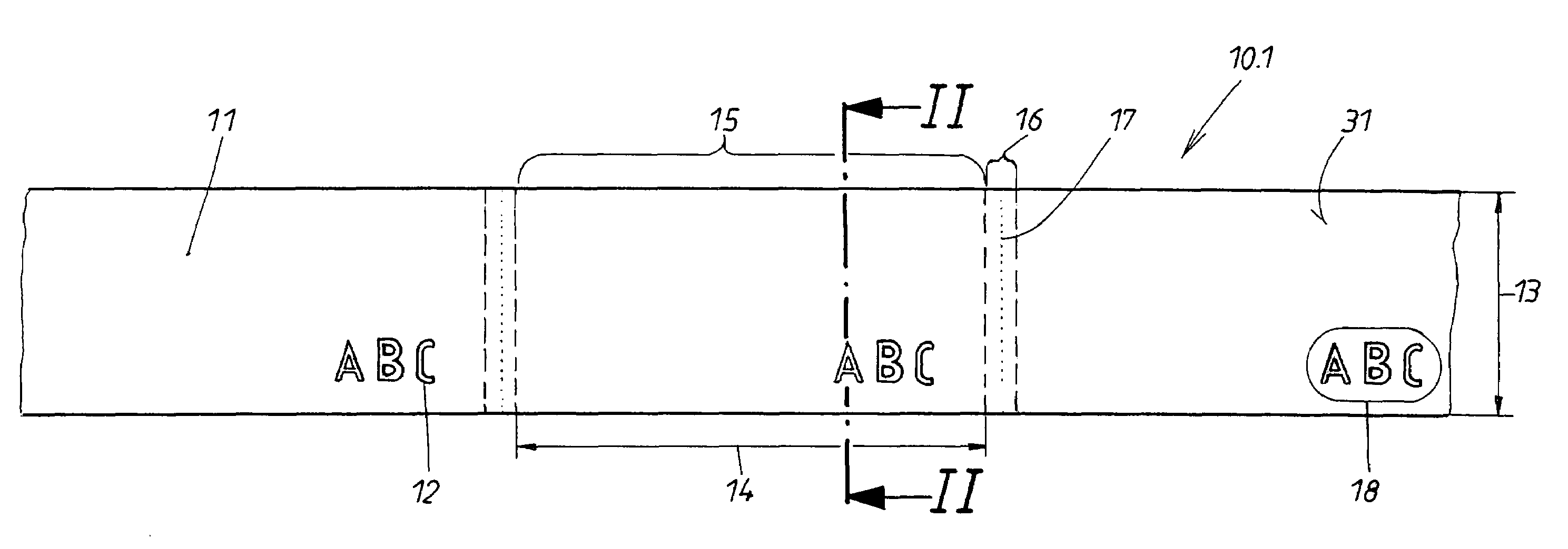
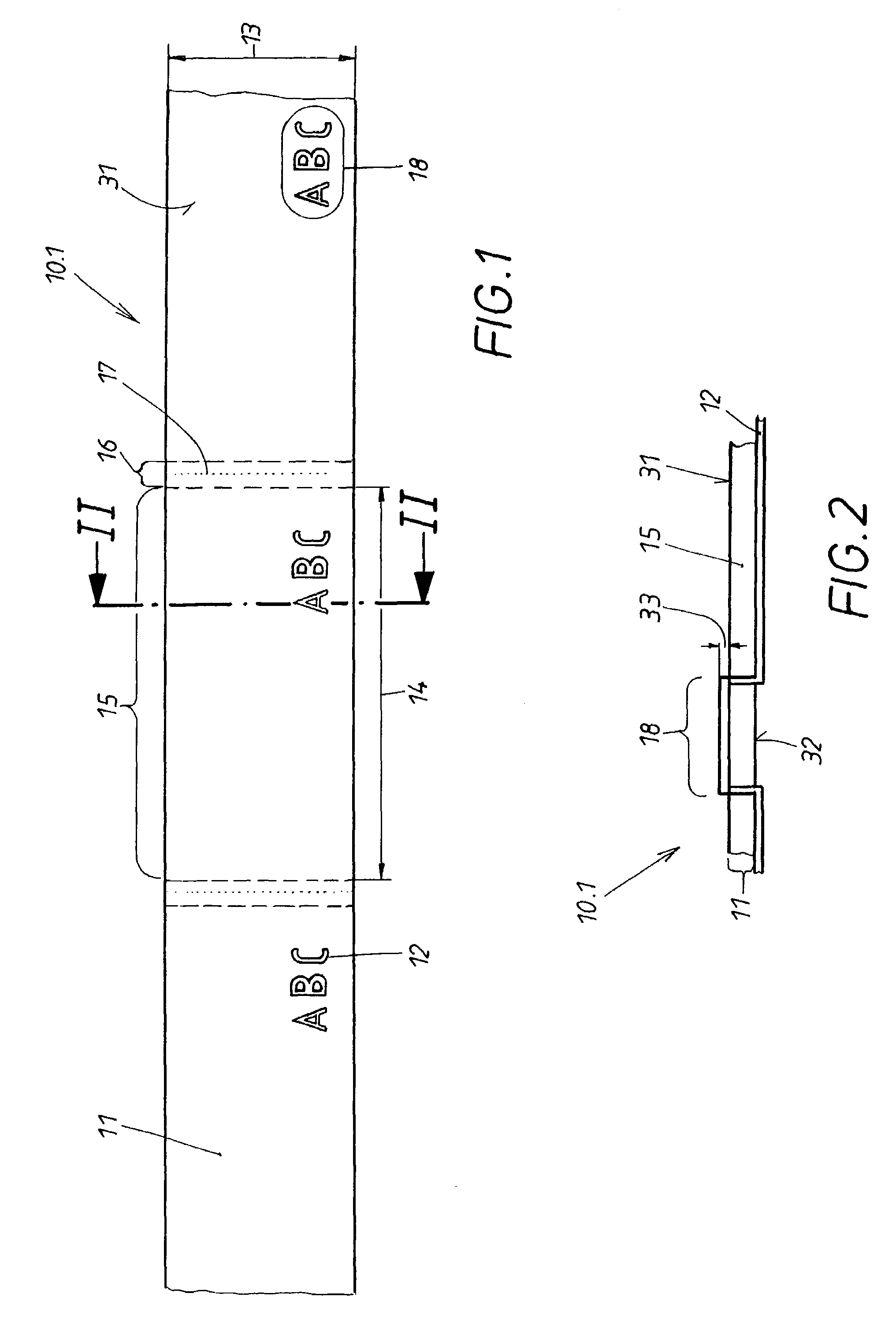
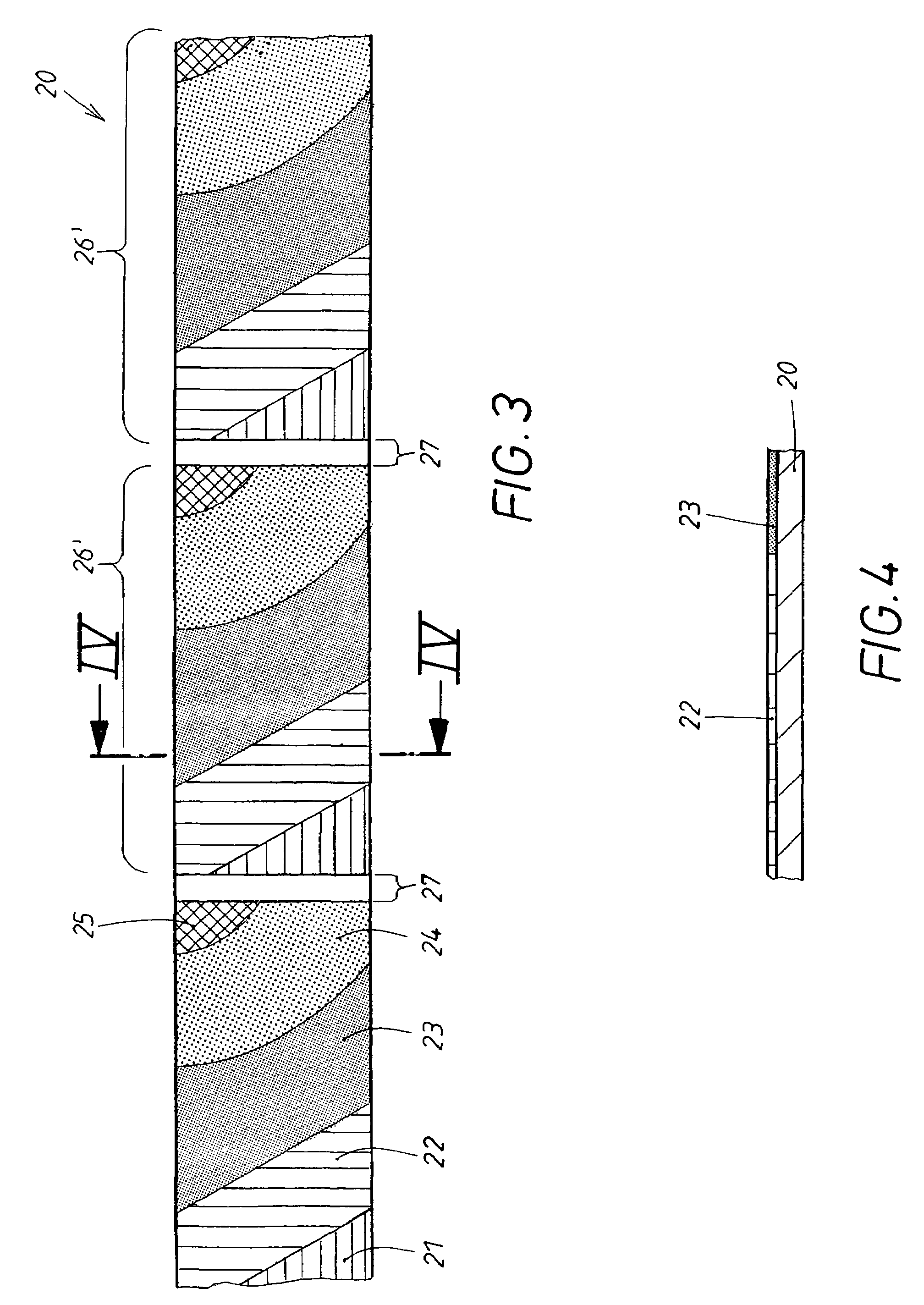
[0026]As already mentioned above, the first method stage of the method according to the present invention will be explained in more detail with the aid of FIG. 1. Initially a web 10.1 is produced which later is to form the ribbon 10. In the illustrated embodiment, the web 10.1 is composed of a woven ribbon which already has the desired ribbon width 13. It is understood that a multi-component web 10.1 can be produced which extends over several ribbons widths, wherein, after the last method stage, individual ribbons 10.1′ to 10.1″″ can be produced on the web 10.1 in the manner which will be described in more detail. If, as is the case in the illustrated embodiment, a label ribbon 10.2 is to be manufactured from the web 10.1, the web width 13 advantageously is already the label width.

[0027]The web 10.1 is manufactured by weaving from two different ribbon materials 11, 12. The first ribbon material 11, whose properties shall be described in more detail in connection with FIG. 3, is comp...


PUM

PropertyMeasurementUnit
colorsaaaaaaaaaa
coloraaaaaaaaaa
surface areasaaaaaaaaaa

Abstract

A method of manufacturing printed textile ribbons reliably and inexpensively, initially a web is produced which forms the later ribbon. The web is composed of two different materials, wherein a figure is applied on one side of the web. The web is subsequently subjected to a heat and pressure treatment with sublimation colors, such that the sublimation colors are absorbed by the first ribbon material and produce on one side a desired printed image. The figure is composed on this side of materials which do not absorb the sublimation colors. As a result, the color of the figure remains unchanged on this side of the ribbon, although the figure had contact with the sublimation colors.

Description

BACKGROUND OF THE INVENTION[0001]1. Field of the Invention[0002]The present invention relates to a method of manufacturing a printed textile ribbon which includes applying at least on one side of the ribbon a printed image having at least one or more colors, and simultaneously producing on the one side of the ribbon a figure in a color which deviates from the color of the printed image.[0003]2. Description of the Related Art[0004]Textile ribbons are frequently attached and sold together with a textile product. The purpose of such a ribbon may be decorative, it may serve as a reflector or as an advertisement carrier, or may also be an integral component of a product, for example, a brassiere strap. It also happens that textile ribbons are sold by themselves, for example, as key ribbons. In many of these types of applications, it is important that the ribbon has an appearance which is as attractive as possible. The purpose is to increase the sales of the product to which the ribbon is...

Claims


Application Information

Patent Timeline
Patent Type & Authority Patents(United States)
IPC IPC(8): B41M5/035B31D1/02B41J2/325B41J31/00D03D1/00D06B11/00D06H1/02D06P5/28G09F3/02
CPCD03D1/0011D06P5/004
Inventor TISCHER, HEINZAUGST, ROLF
Owner AVERY DENNISON RINKE
Learn More